Nissan Pathfinder (2010 year). Manual - part 465
DIAGNOSIS AND REPAIR WORKFLOW
INL-3
< BASIC INSPECTION >
C
D
E
F
G
H
I
J
K
M
A
B
INL
N
O
P
BASIC INSPECTION
DIAGNOSIS AND REPAIR WORKFLOW
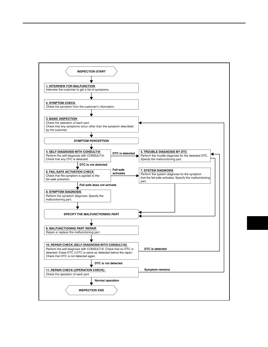
Work Flow
INFOID:0000000005255029
OVERALL SEQUENCE
AWLIA1661GB
2010 Pathfinder