Nissan Pathfinder (2010 year). Manual - part 381
EM-176
< ON-VEHICLE REPAIR >
[VK56DE]
FUEL INJECTOR AND FUEL TUBE
FUEL INJECTOR AND FUEL TUBE
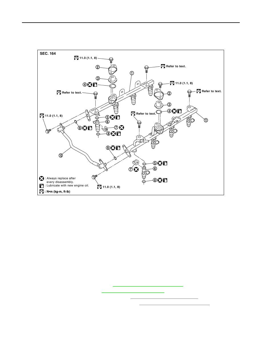
Exploded View
INFOID:0000000005260518
Removal and Installation
INFOID:0000000005260519
CAUTION:
Do not remove or disassemble parts unless instructed as shown.
REMOVAL
WARNING:
• Put a “CAUTION FLAMMABLE” sign in the workshop.
• Be sure to work in a well ventilated area and furnish workshop with a CO
2
fire extinguisher.
• Do not smoke while servicing fuel system. Keep open flames and sparks away from the work area.
• To avoid the danger of being scalded, do not drain engine coolant when engine is hot.
1. Remove the engine room cover. Refer to
EM-160, "Removal and Installation"
2. Release the fuel pressure. Refer to
3. Disconnect the battery negative terminal. Refer to
PG-78, "Removal and Installation"
4. Remove the air duct and resonator assembly. Refer to
EM-161, "Removal and Installation"
5. Disconnect the EVAP canister purge control solenoid valve harness connector.
6. Disconnect the fuel injector harness connectors.
7. Disconnect the fuel hose assembly from the fuel tubes (RH and LH).
1.
Fuel tube (RH)
2.
Cap
3.
Fuel damper
4.
O-ring
5.
O-ring (blue)
6.
Fuel injector
7.
Clip
8.
O-ring (brown)
9.
O-ring
10. Fuel hose assembly
11. Fuel tube (LH)
KBIA2472E
2010 Pathfinder