Nissan Pathfinder (2010 year). Manual - part 379
EM-160
< ON-VEHICLE REPAIR >
[VK56DE]
ENGINE ROOM COVER
ON-VEHICLE REPAIR
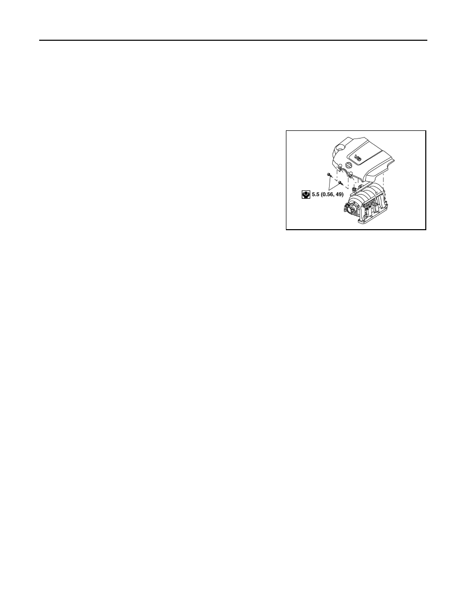
ENGINE ROOM COVER
Removal and Installation
INFOID:0000000005260505
CAUTION:
Do not damage or scratch cover when installing or removing.
REMOVAL
• Remove the engine room cover bolts and engine room cover.
INSTALLATION
Installation is in the reverse order of removal.
ALBIA0414GB
2010 Pathfinder