Nissan Pathfinder (2010 year). Manual - part 166
DOOR SWITCH
DLK-227
< COMPONENT DIAGNOSIS >
[WITHOUT INTELLIGENT KEY SYSTEM]
C
D
E
F
G
H
I
J
L
M
A
B
DLK
N
O
P
Is the inspection result normal?
YES
>> Door switch circuit is OK.
NO
>> GO TO 2
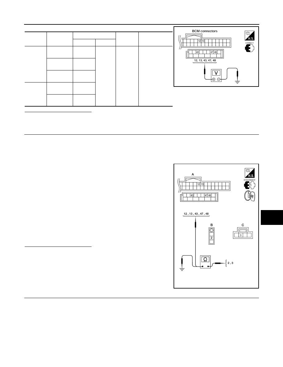
2.
CHECK DOOR SWITCH CIRCUIT
1. Turn ignition switch OFF.
2. Disconnect door switch and BCM.
3. Check continuity between BCM connector (A) M18, M19 terminals 12, 13, 43, 47, 48 and door switch con-
nector (B) B8 (Front LH), B108 (Front RH), B18 (Rear LH), B116 (Rear RH) terminal 2 or back door latch
connector (C) D502 terminal 3.
4. Check continuity between door switch connector (B) B8 (Front
LH), B108 (Front RH), B18 (Rear LH), B116 (Rear RH) terminal
2 or back door latch connector (C) D502 terminal 7 and ground.
Is the inspection result normal?
YES
>> (Front and rear doors) GO TO 3.
YES
>> (Back door) GO TO 4.
NO
>> Repair or replace harness.
3.
CHECK DOOR SWITCH
• Check continuity between door switch terminals.
Connec-
tor
Item
Terminals
Condition
Voltage (V)
(Approx.)
( + )
( – )
M19
Back door
switch/latch
43
Ground
Open
↓
Closed
0
↓
Battery voltage
Front door
switch LH
47
Rear door
switch LH
48
M18
Front door
switch RH
12
Rear door
switch RH
13
LIIA1041E
2 - 47
:Continuity should exist
2 - 12
:Continuity should exist
2 - 48
:Continuity should exist
2 - 13
:Continuity should exist
3 - 43
:Continuity should exist
2 - Ground
:Continuity should not exist
3 - Ground
:Continuity should not exist
ALKIA1701ZZ
2010 Pathfinder