Nissan Pathfinder (2010 year). Manual - part 95


  Index      Manuals     Nissan Pathfinder (2010 year) - Service and Repair Manual


Search            copyright infringement  


Content      ..     93      94      95      96     ..


Nissan Pathfinder (2010 year). Manual - part 95


BR-30

< ON-VEHICLE REPAIR >

BRAKE TUBE AND HOSE

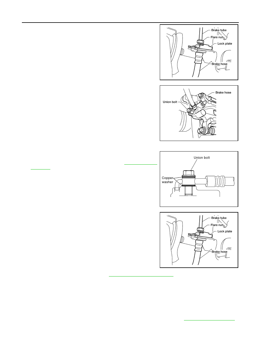
3. Remove brake tube from brake hose, using a suitable tool.
4. Remove lock plate and brake hose from bracket.

5. Remove union bolt and copper washers, then remove brake

hose from caliper assembly.

CAUTION:

Do not reuse copper washer.

INSTALLATION

1. Install brake hose by aligning with the protrusion on caliper

assembly, then install new copper washers and union bolt.

Tighten union bolt to specified torque. Refer to 

BR-26, "Hydrau-

lic Circuit"

.

CAUTION:

Do not reuse copper washers.

2. Insert brake hose end through bracket, then secure it to bracket

with lock plate.

3. Install brake tube to brake hose, then tighten flare nut to the

specified torque using a suitable tool.

4. Refill brake fluid and bleed air. Refer to 

BR-20, "Bleeding Brake System"

.

Inspection After Installation

INFOID:0000000005260211

CAUTION:

Brake tubes and hoses are important safety parts. Always disassemble the parts and retighten their fit-

tings if a brake fluid leak is detected. Replace applicable part with a new one, if a damaged part is

detected.

1. Check brake pipes and hoses, and connections for fluid leaks, damage, twist, deformation, contact with

other parts, and loose connections. Replace any parts as necessary. Refer to 

BR-26, "Hydraulic Circuit"

.

LFIA0238E

LFIA0237E

SFIA1137E

LFIA0238E

2010 Pathfinder

BRAKE TUBE AND HOSE

BR-31

< ON-VEHICLE REPAIR >

C

D

E

G

H

I

J

K

L

M

A

B

BR

N

O

P

2. While depressing brake pedal under a force of 785 N (80 kg-f, 177 lb-f) with engine running for approxi-

mately 5 seconds, check each part for fluid leaks.

2010 Pathfinder

BR-32

< ON-VEHICLE REPAIR >

BRAKE MASTER CYLINDER

BRAKE MASTER CYLINDER

Removal and Installation

INFOID:0000000005260212

Brake Master Cylinder

CAUTION:

Be careful not to splash brake fluid on painted areas; it may cause paint damage. If brake fluid is

splashed on painted areas, wash it away with water immediately. 

REMOVAL

1. Drain the brake fluid. Refer to 

BR-20, "Drain and Refill"

.

2. Disconnect the harness connectors for the fluid level sensor and fluid pressure sensor.
3. Disconnect the brake pipes from the master cylinder assembly.
4. Remove the master cylinder assembly nuts and discard.

CAUTION:

Discard the nuts, do not reuse.

AWFIA0462GB

1.

Reservoir cap

2.

Strainer

3.

Fluid level sensor

4.

Reservoir tank

5.

Grommet

6.

Restriction washer

7.

Master cylinder sub-assembly

8.

Fluid pressure sensor

9.

O-ring

10. Brake booster

11. Pin

A.

PBC (Poly Butyl Cuprysil) grease 
or silicone based grease

B.

Brake fluid

R.

Rubber grease

Front

2010 Pathfinder

BRAKE MASTER CYLINDER

BR-33

< ON-VEHICLE REPAIR >

C

D

E

G

H

I

J

K

L

M

A

B

BR

N

O

P

5. Remove the master cylinder assembly.

INSTALLATION

Installation is in the reverse order of removal.

• Use new master cylinder assembly nuts for installation.

CAUTION:

Do not reuse the master cylinder assembly nuts.

• Refill the brake fluid and bleed the air. Refer to 

BR-20, "Bleeding Brake System"

.

CAUTION:

• Refill using recommended brake fluid. Refer to 

BR-20, "Drain and Refill"

.

• Do not reuse drained brake fluid.

• Adjust the brake pedal. Refer to 

BR-17, "Inspection and Adjustment - Standard Pedal"

BR-18, "Inspection

and Adjustment - Adjustable Pedal"

.

• Apply silicon grease to the brake booster at position (A) as shown

when installing the master cylinder assembly to the brake booster.

JPFIA0013ZZ

2010 Pathfinder

BR-34

< ON-VEHICLE REPAIR >

BRAKE BOOSTER

BRAKE BOOSTER

Removal and Installation

INFOID:0000000005260213

Brake Booster and Vacuum Hose

REMOVAL 

CAUTION:

• Be careful not to deform or bend brake piping while removing and installing brake booster.

• Replace clevis pin if it is damaged.

• Be careful not to damage brake booster stud bolt threads. If brake booster is tilted or inclined during

installation, dash panel may damage the threads.

• Attach the check valve in the correct direction.

1. Remove the ABS actuator and electric unit (control unit). Refer to 

BRC-127, "Removal and Installation"

.

2. Remove the brake master cylinder. Refer to 

BR-32, "Removal and Installation"

.

AWFIA0463GB

1.

Brake booster vacuum hose

2.

Brake booster vacuum check valve 3.

Brake booster

4.

Lock nut

5.

Gasket

6.

Spacer block

Front

2010 Pathfinder

BRAKE BOOSTER

BR-35

< ON-VEHICLE REPAIR >

C

D

E

G

H

I

J

K

L

M

A

B

BR

N

O

P

3. Remove brake booster vacuum hose from the brake booster. Refer to 

BR-36, "Removal and Installation"

.

4. Remove the brake pedal clevis pin (2) and snap pin (1) from

inside the vehicle. 

5. Remove the brake booster and brake pedal assembly nuts and discard.

CAUTION:

Discard the nuts, do not reuse.

6. Remove brake booster assembly from dash panel.

INSTALLATION

1. Loosen the lock nut (1) to adjust the input rod (2) so that length

(A) is within the specified value.

2. After adjusting input rod length (A), temporarily tighten the lock

nut (1) and install the booster assembly to the dash panel.

• Install a gaskets and spacer block between the booster

assembly and the dash panel.

3. Connect the input rod using the brake pedal clevis pin (2) and

snap pin (1) from inside the vehicle. 

4. Install the brake booster using new nuts.

CAUTION:

Do not reuse the brake booster and brake pedal assembly nuts.

5. Connect the brake booster vacuum hose and check valve to the brake booster.
6. Install the brake master cylinder. Refer to 

BR-32, "Removal and Installation"

.

7. Adjust the brake pedal height. Refer to 

BR-17, "Inspection and Adjustment - Standard Pedal"

BR-18,

"Inspection and Adjustment - Adjustable Pedal"

.

8. Tighten the input rod lock nut to specification.
9. Refill with new brake fluid and bleed the air. Refer to 

BR-20, "Bleeding Brake System"

.

JPFIA0019ZZ

Input rod (2) with lock nut (1) 
length (A) standard dimension

: Refer to 

BR-57, "Brake 

Booster"

.

JPFIA0238ZZ

JPFIA0019ZZ

2010 Pathfinder

BR-36

< ON-VEHICLE REPAIR >

VACUUM LINES

VACUUM LINES

Removal and Installation

INFOID:0000000005260214

Brake Booster Vacuum Hose

REMOVAL

1. Disconnect brake booster hose from hose clip bracket.
2. Release the brake booster hose clips and remove the brake booster hose. 
3. Remove the check valve from the brake booster.

INSTALLATION

Installation is in the reverse order of removal.

• Insert vacuum hose onto tube and brake booster vacuum check

valve for a minimum length (A) before installing the brake booster

hose clips.

CAUTION:

Do not use lubricating oil during installation.

WFIA0332E

1.

Brake booster hose

2.

Brake booster hose clip

3.

Brake booster vacuum check valve

Vacuum hose length (A)

: 24 mm (0.94 in) or more

JPFIA0023ZZ

2010 Pathfinder

FRONT DISC BRAKE

BR-37

< ON-VEHICLE REPAIR >

C

D

E

G

H

I

J

K

L

M

A

B

BR

N

O

P

FRONT DISC BRAKE

Exploded View of Brake Pads

INFOID:0000000005260215

Front Brake Pads, Shims and Retainers VQ40

AWFIA0594ZZ

1.

Inner shim cover

2.

Inner shim

3.

Upper pad retainer

4.

Lower pad retainer

5.

Inner brake pad

6.

Outer brake pad

7.

Outer shim

A.

Molykote AS-880N grease

B.

Molykote 7439 grease

2010 Pathfinder


Content      ..     93      94      95      96     ..