Nissan Pathfinder (2010 year). Manual - part 93


  Index      Manuals     Nissan Pathfinder (2010 year) - Service and Repair Manual


Search            copyright infringement  


Content      ..     91      92      93      94     ..


Nissan Pathfinder (2010 year). Manual - part 93


BR-14

< BASIC INSPECTION >

BRAKE TUBE AND HOSE

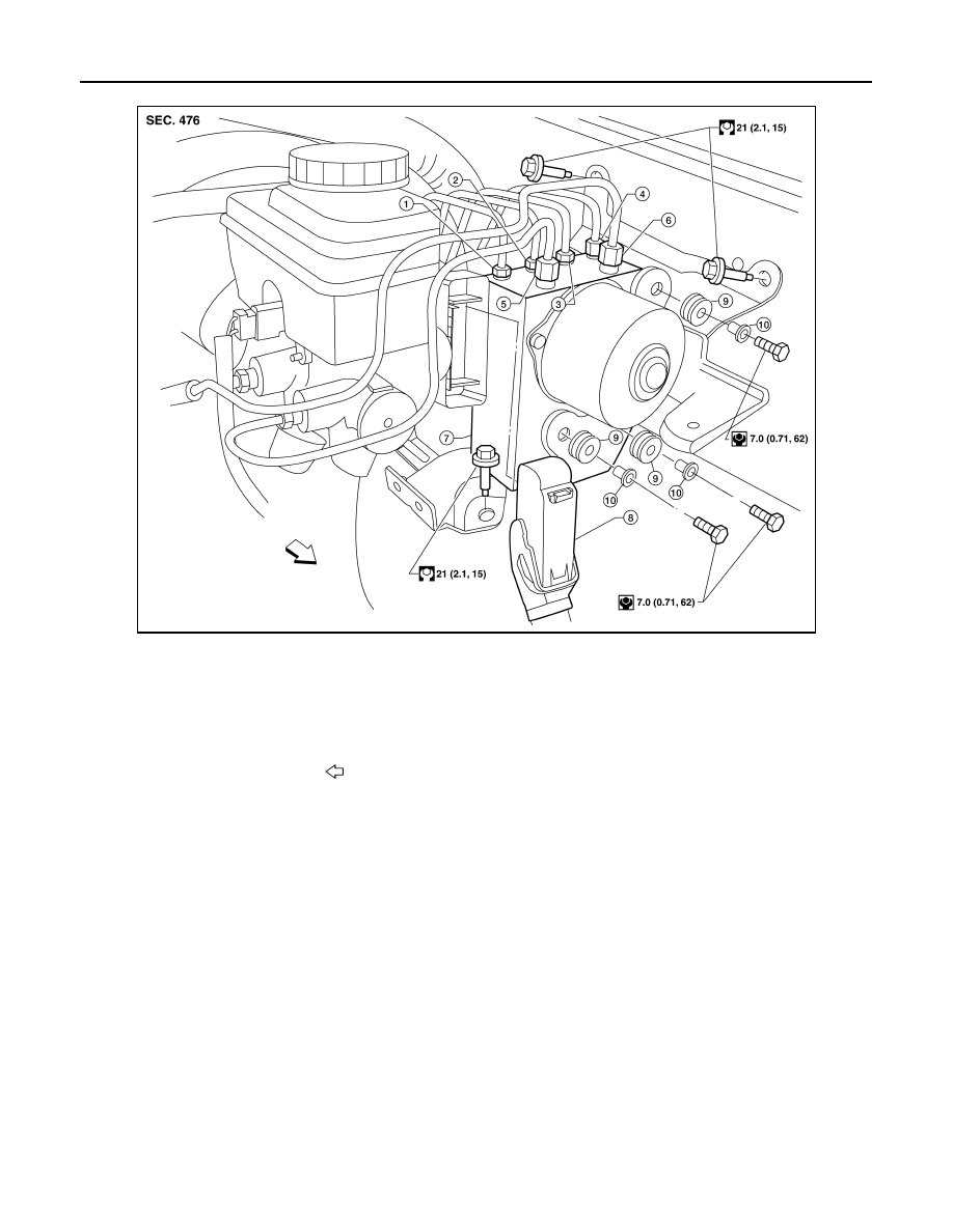
ABS Actuator and Electric Unit Brake Pipe Connections for VK56DE

AWFIA0593GB

1.

To rear left disc brake
13.0 N·m (1.3 kg-m, 10 ft-lb)

2.

To rear right disc brake
13.0 N·m (1.3 kg-m, 10 ft-lb)

3.

To front left disc brake
13.0 N·m (1.3 kg-m, 10 ft-lb)

4.

To front right disc brake
13.0 N·m (1.3 kg-m, 10 ft-lb)

5.

From the master cylinder secondary side
18.2 N·m (1.9 kg-m, 13 ft-lb)

6.

From the master cylinder primary side
18.2 N·m (1.9 kg-m, 13 ft-lb)

7.

ABS actuator and electric unit 
(control unit)

8.

Harness connector

9.

Grommet

10. Collar

Front

2010 Pathfinder

BRAKE TUBE AND HOSE

BR-15

< BASIC INSPECTION >

C

D

E

G

H

I

J

K

L

M

A

B

BR

N

O

P

ABS Actuator and Electric Unit Brake Pipe Connections for VQ40DE

CAUTION:

• All hoses and piping (tubes) must be free from excessive bending, twisting and pulling.

• Make sure there is no interference with other parts when turning the steering wheel both clockwise

and counterclockwise.

• The brake piping is an important safety part. If a brake fluid leak is detected, always disassemble the

parts. Replace applicable part with a new one, if necessary.

• Be careful not to splash brake fluid on painted areas; it may cause paint damage. If brake fluid is

splashed on painted areas, wash it away with water immediately.

• Do not bend or twist brake hose sharply, or strongly pull it.

• When removing components, cover connections so that no dirt, dust, or other foreign matter gets in.

• Refill with new specified brake fluid. Refer to 

MA-16, "For North America"

.

• Do not reuse drained brake fluid.

FRONT BRAKE
FRONT BRAKE : Inspection

INFOID:0000000005260199

INSPECTION AFTER REMOVAL

CAUTION:

Brake tubes and hoses are important safety parts. Always disassemble the parts and retighten their fit-

tings, if a brake fluid leak is detected. Replace applicable part with a new one, if damaged part is

detected. 

ALFIA0146ZZ

1.

From master cylinder secondary side
18.2 N·m (1.9 kg-m, 13 ft-lb)

2.

To rear right disc brake
13.0 N·m (1.3 kg-m, 10 ft-lb)

3.

To rear left disc brake
13.0 N·m (1.3 kg-m, 10 ft-lb)

4.

To front right disc brake
13.0 N·m (1.3 kg-m, 10 ft-lb)

5.

To front left disc brake
13.0 N·m (1.3 kg-m, 10 ft-lb)

6.

From master cylinder primary side
18.2 N·m (1.9 kg-m, 13 ft-lb)

7.

ABS actuator and electric unit (control 
unit)

8.

Harness connector

Front

2010 Pathfinder

BR-16

< BASIC INSPECTION >

BRAKE TUBE AND HOSE

1. Check brake lines (tubes and hoses) and connections for fluid leaks, damage, twists, deformation, contact

with other parts, and loose connections. Replace any parts as necessary. Refer to 

BR-13, "Hydraulic Cir-

cuit"

.

2. While depressing brake pedal under a force of 785 N (80 kg-f, 177 lb-f) with engine running for approxi-

mately 5 seconds, check each part for fluid leaks.

REAR BRAKE
REAR BRAKE : Inspection

INFOID:0000000005260200

INSPECTION AFTER REMOVAL

CAUTION:

Brake tubes and hoses are important safety parts. Always disassemble the parts and retighten their fit-

tings, if a brake fluid leak is detected. Replace applicable part with a new one, if damaged part is

detected. 

1. Check brake lines (tubes and hoses) and connections for fluid leaks, damage, twists, deformation, contact

with other parts, and loose connections. Replace any parts as necessary. Refer to 

BR-13, "Hydraulic Cir-

cuit"

.

2. While depressing brake pedal under a force of 785 N (80 kg-f, 177 lb-f) with engine running for approxi-

mately 5 seconds, check each part for fluid leaks.

2010 Pathfinder

BRAKE PEDAL

BR-17

< ON-VEHICLE MAINTENANCE >

C

D

E

G

H

I

J

K

L

M

A

B

BR

N

O

P

ON-VEHICLE MAINTENANCE

BRAKE PEDAL

Inspection and Adjustment - Standard Pedal

INFOID:0000000005260201

INSPECTION

1. Inspect the brake pedal free height (H) from the floor using Tool

at a 90

°

 angle to the floor as shown. 

2. Adjust the brake pedal height to specifications.

Brake Pedal Specifications

Unit: mm (in)

ADJUSTMENT

1. Loosen the stop lamp switch and ASCD cancel switch by turning 45

°

 counterclockwise.

Tool number : 

(J-46532)

AWFIA0557ZZ

Pedal free height (H)

Refer to 

BR-56, "Brake Pedal"

.

Pedal full stroke (S)
[Depressed under a force of 490 N (50 kg, 110 lb) with engine running]

Refer to 

BR-56, "Brake Pedal"

.

Clearance between pedal stopper and threaded end of stop lamp switch and ASCD 
switch (C

1

) or (C

2

)

Refer to 

BR-56, "Brake Pedal"

.

2010 Pathfinder

BR-18

< ON-VEHICLE MAINTENANCE >

BRAKE PEDAL

2. Loosen lock nut (A) on the input rod, then turn input rod to adjust

the brake pedal to specified height. When finished adjusting,

tighten lock nut (A) to specification.

CAUTION:

Make sure that the screw portion of the end of input rod is

located inside the clevis.

3. With the brake pedal pulled up and held by hand, press the stop

lamp switch and the ASCD cancel switch in until threaded ends

contact the brake pedal bracket. 

4. With the threaded ends of the stop lamp switch and ASCD

switch contacting the pedal bracket, turn the switches 45

°

 clock-

wise to lock in place. Check that the stop lamp switch and ASCD

cancel switch threaded end to brake pedal bracket gap (C) is

within specifications.

CAUTION:

Make sure that the gap (C) between the brake pedal bracket

and stop lamp switch and ASCD cancel switch threaded

ends are within specification.

5. Check the brake pedal for smooth operation.

CAUTION:

Make sure that the stop lamp goes off when the brake pedal

is released.

6. Start the engine and check the height of the brake pedal when depressing it.

Inspection and Adjustment - Adjustable Pedal

INFOID:0000000005260202

INSPECTION

1. Inspect the brake pedal free height (H) from the floor using Tool

at a 90

°

 angle to the floor as shown. 

2. Adjust the height referring to the following specifications.

CAUTION:

When equipped with adjustable pedal, the pedal must be in

the forward most (closest to the floor) position for pedal

height measurement.

Brake Pedal Specifications

Unit: mm (in)

Lock nut (A)

: 18.7 N·m (1.9 kg-m, 14 ft-lb)

PFIA0436E

Tool number : 

(J-46532)

ALFIA0149ZZ

Pedal free height (H) with pedal in forward most position

Refer to 

BR-56, "Brake Pedal"

.

2010 Pathfinder

BRAKE PEDAL

BR-19

< ON-VEHICLE MAINTENANCE >

C

D

E

G

H

I

J

K

L

M

A

B

BR

N

O

P

CAUTION:

When equipped with adjustable pedal, the pedal must be in the forward most position (closest to the floor) for pedal
height adjustment.

ADJUSTMENT

1. Loosen the stop lamp switch and ASCD cancel switch by turning them 45

°

 counterclockwise.

2. Loosen lock nut (A) on the input rod, then turn input rod to adjust

the brake pedal to the specified height. When finished adjusting,

tighten the lock nut (A) to specification.

CAUTION:

Make sure that the screw portion of the end of input rod is

located inside the clevis.

3. With the brake pedal pulled up and held by hand, press the stop

lamp switch and the ASCD cancel switch in until the threaded

ends contact the brake pedal bracket. 

4. With the threaded ends of the stop lamp switch and ASCD

switch contacting the pedal bracket, turn the switches 45

°

 clock-

wise to lock in place. Check that the stop lamp switch and ASCD

cancel switch threaded end to brake pedal bracket gap (C) is

within specifications.

CAUTION:

Make sure that the gap (C) between the brake pedal bracket

and stop lamp switch and ASCD cancel switch threaded

ends are within specification.

5. Check the brake pedal for smooth operation.

CAUTION:

Make sure that the stop lamp goes off when the brake pedal

is released.

6. Start the engine and check the height of the brake pedal when depressing it.

Pedal travel (T)
[Depressed under a force of 490 N (50 kg, 110 lb) with engine running]

Refer to 

BR-56, "Brake Pedal"

.

Clearance between pedal stopper and threaded end of stop lamp switch and ASCD switch

Refer to 

BR-56, "Brake Pedal"

.

Lock nut (A)

: 18.7 N·m (1.9 kg-m, 14 ft-lb)

PFIA0436E

2010 Pathfinder

BR-20

< ON-VEHICLE MAINTENANCE >

BRAKE FLUID

BRAKE FLUID

On Board Inspection

INFOID:0000000005260203

LEVEL CHECK

• Check that the brake fluid level in the reservoir tank is within speci-

fication, between the MAX and MIN lines as shown.

• Visually check around reservoir tank for fluid leaks.

• If fluid level is excessively low, check brake system for leaks.

• If brake warning lamp remains illuminated after the parking brake

pedal is released, check the brake system for any brake fluid

leaks.

Drain and Refill

INFOID:0000000005260204

CAUTION:

• Refill with new brake fluid. Refer to 

MA-16, "For North America"

.

• Do not reuse drained brake fluid.

• Do not let brake fluid splash on the painted surfaces of the body. This might damage the paint, so

when splashing it, immediately wipe off the area and wash away with water.

• Before servicing, disconnect ABS actuator and electric unit (control unit) connector or battery nega-

tive terminal.

1. Turn ignition switch OFF and disconnect ABS actuator and electric unit (control unit) connector or battery

negative terminal.

2. Connect a vinyl tube to each bleed valve.
3. Depress brake pedal, loosen each bleed valve, and gradually

remove brake fluid.

4. Make sure there is no foreign material in reservoir tank, and refill

with new brake fluid.

5. Rest foot on brake pedal. Loosen bleed valve. Slowly depress

brake pedal until it stops. Tighten bleed valve. Release brake

pedal. Repeat the process a few times, then pause to add new

brake fluid to master cylinder. Continue until the new brake fluid

flows out of the bleed valve.

Bleed the air out of the brake hydraulic system. Refer to 

BR-20,

"Bleeding Brake System"

.

Bleeding Brake System

INFOID:0000000005260205

CAUTION:

• Refill with new brake fluid. Refer to 

MA-16, "For North America"

.

• Do not reuse drained brake fluid.

LFIA0234E

BRA0007D

PFIA0403J

2010 Pathfinder

BRAKE FLUID

BR-21

< ON-VEHICLE MAINTENANCE >

C

D

E

G

H

I

J

K

L

M

A

B

BR

N

O

P

• Do not let brake fluid splash on the painted surfaces of the body. This might damage the paint, so

when splashing it, immediately wipe off the area and wash away with water.

• Before servicing, disconnect ABS actuator and electric unit (control unit) connector or battery nega-

tive terminal.

• While bleeding, monitor the master cylinder brake fluid level.

1. Turn ignition switch OFF and disconnect ABS actuator and electric unit (control unit) connector or battery

negative terminal.

2. Connect a vinyl tube to the rear right bleed valve.
3. Fully depress brake pedal 4 to 5 times.
4. With brake pedal depressed, loosen bleed valve to let the air out, and then tighten it immediately.
5. Repeat steps 3 and 4 until no more air comes out.
6. Tighten bleed valve to the specified torque. Refer to 

BR-40, "Exploded View of Brake Caliper"

 (front disc

brake), 

BR-45, "Exploded View of Brake Caliper"

 (rear disc brake). 

7. Perform steps 2 to 6 at each wheel, with master cylinder reservoir tank filled at least half way, bleed air

from the front left, rear left, and front right bleed valve, in that order.

2010 Pathfinder


Content      ..     91      92      93      94     ..