Nissan Pathfinder (2010 year). Manual - part 8
ADP-50
< COMPONENT DIAGNOSIS >
RECLINING SWITCH
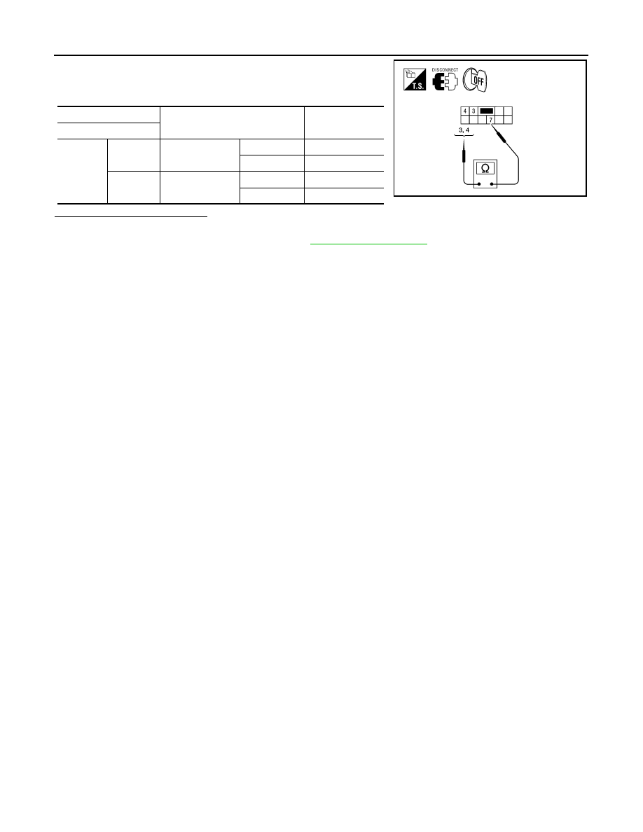
1. Turn ignition switch OFF.
2. Disconnect power seat switch LH.
3. Check continuity between power seat switch LH terminals.
Is the inspection result normal?
YES
>> Inspection End.
NO
>> Replace power seat switch LH. Refer to
.
Terminals
Condition
Continuity
Power seat switch LH
7
3
Reclining switch
(backward)
Operate
Yes
Release
No
4
Reclining switch
(forward)
Operate
Yes
Release
No
ALJIA0311ZZ
2010 Pathfinder