Nissan Pathfinder (2009 year). Manual - part 321


  Index      Manuals     Nissan Pathfinder (2009 year) - Service and Repair Manual


Search            copyright infringement  


Content      ..     319      320      321      322     ..


Nissan Pathfinder (2009 year). Manual - part 321


EC-582

< COMPONENT DIAGNOSIS >

[VK56DE]

P0037, P0038, P0057, P0058 HO2S2 HEATER

6.

Let engine idle for 1 minute.

7.

Check 1st trip DTC.

8.

If 1st trip DTC is detected, go to 

EC-582, "Diagnosis Procedure"

.

Diagnosis Procedure

INFOID:0000000003936505

1.

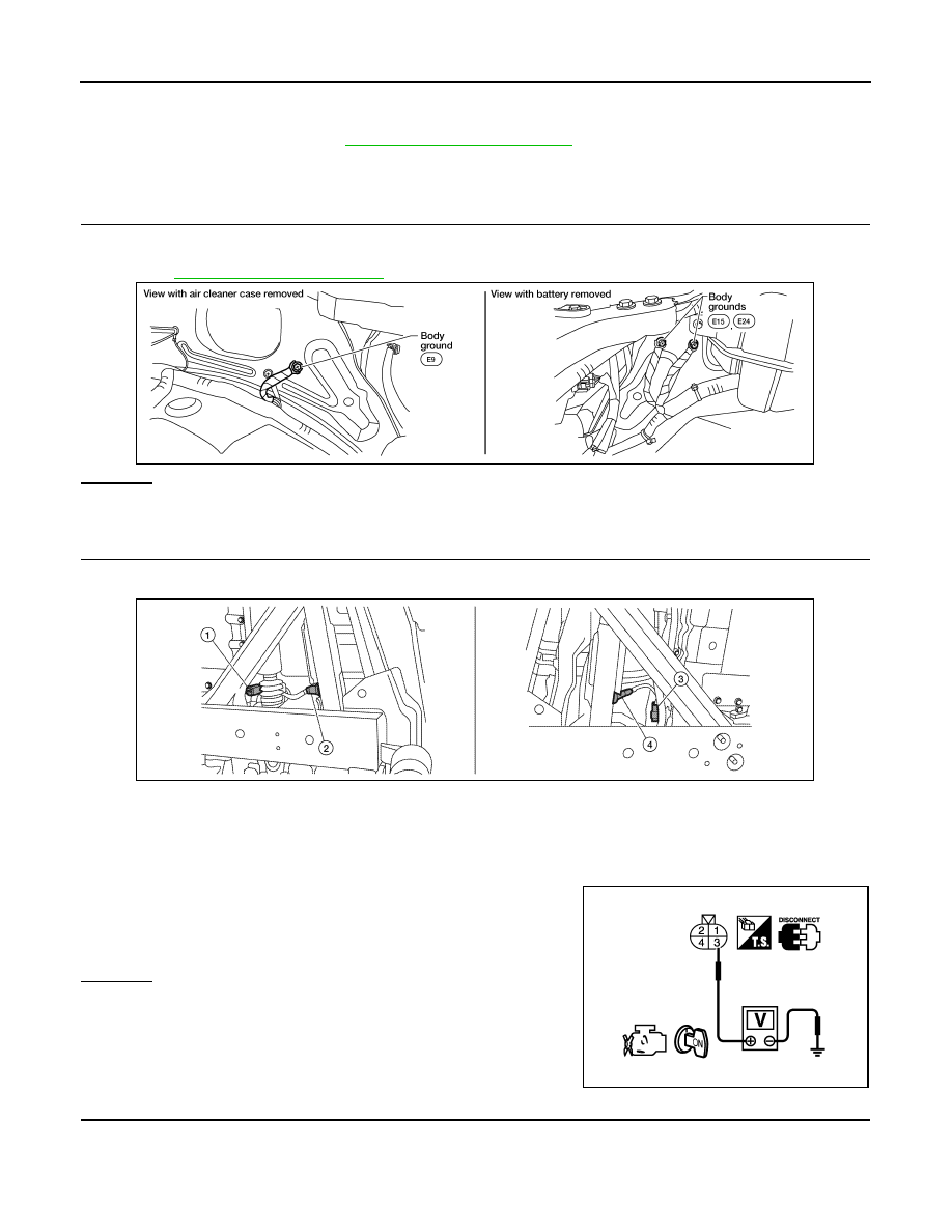
CHECK GROUND CONNECTIONS

1.

Turn ignition switch OFF.

2.

Loosen and retighten ground screws on the body.
Refer to 

EC-568, "Ground Inspection"

.

OK or NG

OK

>> GO TO 2.

NG

>> Repair or replace ground connections.

2.

CHECK HEATED OXYGEN SENSOR 2 HEATER POWER SUPPLY CIRCUIT

1.

Disconnect heated oxygen sensor 2 (HO2S2) harness connector.

2.

Turn ignition switch ON.

3.

Check voltage between HO2S2 terminal 3 and ground with
CONSULT-III or tester.

OK or NG

OK

>> GO TO 4.

NG

>> GO TO 3.

3.

DETECT MALFUNCTIONING PART

Check the following.
• Harness connectors E2, F32
• IPDM E/R harness connector E119

BBIA0539E

1.

Heated oxygen sensor 2 (bank 1) 
harness connector

2.

Heated oxygen sensor 2 (bank 1)

3.

Heated oxygen sensor (bank 2) har-
ness connector

4.

Heated oxygen sensor 2 (bank 2)

Voltage: Battery voltage

ALBIA0365ZZ

PBIB0112E

2009 Pathfinder

P0037, P0038, P0057, P0058 HO2S2 HEATER

EC-583

< COMPONENT DIAGNOSIS >

[VK56DE]

C

D

E

F

G

H

I

J

K

L

M

A

EC

N

P

O

• 15 A fuse (No. 54)
• Harness for open or short between heated oxygen sensor 2 and IPDM E/R

>> Repair harness or connectors.

4.

CHECK HO2S2 HEATER OUTPUT SIGNAL CIRCUIT FOR OPEN AND SHORT

1.

Turn ignition switch OFF.

2.

Disconnect ECM harness connector.

3.

Check harness continuity between ECM terminal and HO2S2 terminal as per the following.
Refer to Wiring Diagram.

4.

Also check harness for short to ground and short to power.

OK or NG

OK

>> GO TO 5.

NG

>> Repair open circuit or short to ground or short to power in harness or connectors.

5.

CHECK HEATED OXYGEN SENSOR 2 HEATER

Refer to 

EC-583, "Component Inspection"

.

OK or NG

OK

>> GO TO 6.

NG

>> Replace malfunctioning heated oxygen sensor 2.

6.

CHECK INTERMITTENT INCIDENT

Refer to 

GI-49, "Intermittent Incident"

.

>> INSPECTION END

Component Inspection

INFOID:0000000003936506

HEATED OXYGEN SENSOR 2 HEATER

DTC

Terminals

Bank

ECM

Sensor

P0037, P0038

6

2

1

P0057, P0058

25

2

2

Continuity should exist.

2009 Pathfinder

EC-584

< COMPONENT DIAGNOSIS >

[VK56DE]

P0037, P0038, P0057, P0058 HO2S2 HEATER

1.

Check resistance between HO2S2 terminals as per the follow-
ing.

2.

If NG, replace heated oxygen sensor 2.

CAUTION:

• Discard any heated oxygen sensor which has been dropped

from a height of more than 0.5 m (19.7 in) onto a hard surface
such as a concrete floor; use a new one.

• Before installing new heated oxygen sensor, clean exhaust

system threads using Oxygen Sensor Thread Cleaner [Com-
mercial service tool (J-43897-18 or J-43897-12)] and approved
Anti-seize Lubricant (Commercial service tool).

Terminal No.

Resistance [at 25

°

C (77

°

F)]

2 and 3

8 - 10 

1 and 2, 3, 4


(Continuity should not exist)

4 and 1, 2, 3

SEF249Y

2009 Pathfinder

P0075, P0081 IVT CONTROL SOLENOID VALVE

EC-585

< COMPONENT DIAGNOSIS >

[VK56DE]

C

D

E

F

G

H

I

J

K

L

M

A

EC

N

P

O

P0075, P0081 IVT CONTROL SOLENOID VALVE

Component Description

INFOID:0000000003936507

Intake valve timing control solenoid valve is activated by ON/OFF
pulse duty (ratio) signals from the ECM.
The intake valve timing control solenoid valve changes the oil
amount and direction of flow through intake valve timing control unit
or stops oil flow.
The longer pulse width advances valve angle.
The shorter pulse width retards valve angle.
When ON and OFF pulse widths become equal, the solenoid valve
stops oil pressure flow to fix the intake valve angle at the control
position.

On Board Diagnosis Logic

INFOID:0000000003936508

DTC Confirmation Procedure

INFOID:0000000003936509

1.

If DTC Confirmation Procedure has been previously conducted, always perform the following procedure
before conducting the next step.

a.

Turn ignition switch OFF and wait at least 10 seconds.

b.

Turn ignition switch ON.

c.

Turn ignition switch OFF and wait at least 10 seconds.

2.

Start engine and let it idle for 5 seconds.

3.

Check 1st trip DTC.

4.

If 1st trip DTC is detected, go to 

EC-585, "Diagnosis Procedure"

.

Diagnosis Procedure

INFOID:0000000003936510

1.

CHECK INTAKE VALVE TIMING CONTROL SOLENOID VALVE POWER SUPPLY CIRCUIT

1.

Turn ignition switch OFF.

2.

Disconnect intake valve timing control solenoid valve harness connector.

PBIB1842E

DTC No.

Trouble diagnosis name

DTC detecting condition

Possible cause

P0075
0075
(Bank 1)

Intake valve timing control 
solenoid valve circuit

An improper voltage is sent to the ECM 
through intake valve timing control solenoid 
valve.

• Harness or connectors

(Intake valve timing control solenoid valve 
circuit is open or shorted.)

• Intake valve timing control solenoid valve

P0081
0081
(Bank 2)

BBIA0771E

2009 Pathfinder

EC-586

< COMPONENT DIAGNOSIS >

[VK56DE]

P0075, P0081 IVT CONTROL SOLENOID VALVE

3.

Turn ignition switch ON.

4.

Check voltage between intake valve timing control solenoid
valve terminal 2 and ground with CONSULT-III or tester.

OK or NG

OK

>> GO TO 3.

NG

>> GO TO 2.

2.

DETECT MALFUNCTIONING PART

Check the following.
• Harness connectors E2, F32
• IPDM E/R harness connector E119
• Harness for open or short between intake valve timing control solenoid valve and IPDM E/R

>> Repair open circuit or short to ground or short to power in harness or connectors.

3.

CHECK INTAKE VALVE TIMING CONTROL SOLENOID VALVE OUTPUT SIGNAL CIRCUIT FOR OPEN

AND SHORT

1.

Turn ignition switch OFF.

2.

Disconnect ECM harness connector.

3.

Check harness continuity between the following;
ECM terminal 10 and intake valve timing control solenoid valve (bank 1) terminal 1 or
ECM terminal 11 and intake valve timing control solenoid valve (bank 2) terminal 1.
Refer to Wiring Diagram.

4.

Also check harness for short to ground and short to power. 

OK or NG

OK

>> GO TO 4.

NG

>> Repair open circuit or short to ground or short to power in harness or connectors.

4.

CHECK INTAKE VALVE TIMING CONTROL SOLENOID VALVE

Refer to 

EC-586, "Component Inspection"

.

OK or NG

OK

>> GO TO 5.

NG

>> Replace malfunctioning intake valve timing control solenoid valve.

5.

CHECK INTERMITTENT INCIDENT

Refer to 

GI-49, "Intermittent Incident"

.

>> INSPECTION END

Component Inspection

INFOID:0000000003936511

INTAKE VALVE TIMING CONTROL SOLENOID VALVE

1.

Disconnect intake valve timing control solenoid valve harness connector.

1.

Intake valve timing control position 
sensor (bank 2)

2.

Intake valve timing control solenoid 
valve (bank 2)

3.

Drive belt

4.

Radiator hose

5.

Intake valve timing control solenoid 
valve (bank 1)

6.

Intake valve timing control position 
sensor (bank 1)

Voltage: Battery voltage

PBIB0192E

Continuity should exist.

2009 Pathfinder

P0075, P0081 IVT CONTROL SOLENOID VALVE

EC-587

< COMPONENT DIAGNOSIS >

[VK56DE]

C

D

E

F

G

H

I

J

K

L

M

A

EC

N

P

O

2.

Check resistance between intake valve timing control solenoid
valve terminals as per the following.

If NG, replace intake valve timing control solenoid valve.
If OK, go to next step.

3.

Remove intake valve timing control solenoid valve.

4.

Provide 12 V DC between intake valve timing control solenoid
valve terminals and then interrupt it. Check that the plunger
moves as shown in the figure.

CAUTION:

Never apply 12 V DC continuously for 5 seconds or more.
Doing so may result in damage to the coil in intake valve
timing control solenoid valve.
If NG, replace intake valve timing control solenoid valve.
NOTE:
Always replace O-ring when intake valve timing control
solenoid valve is removed.

Terminals

Resistance [at 20

°

C (68

°

F)]

1 and 2

7.1 - 7.7 

1 or 2 and ground


(Continuity should not exist)

PBIB0193E

PBIB2275E

2009 Pathfinder

EC-588

< COMPONENT DIAGNOSIS >

[VK56DE]

P0101 MAF SENSOR

P0101 MAF SENSOR

Component Description

INFOID:0000000004333335

The mass air flow sensor is placed in the stream of intake air. It mea-
sures the intake flow rate by measuring a part of the entire intake
flow. The mass air flow sensor controls the temperature of the hot
wire to a certain amount. The heat generated by the hot wire is
reduced as the intake air flows around it. The greater air flow, the
greater the heat loss.
Therefore, the electric current supplied to the hot wire is changed to
maintain the temperature of the hot wire as air flow increases. The
ECM detects the air flow by means of this current change.

On Board Diagnosis Logic

INFOID:0000000003936513

DTC Confirmation Procedure

INFOID:0000000003936514

Perform PROCEDURE FOR MALFUNCTION A first.
If the DTC cannot be confirmed, perform PROCEDURE FOR MALFUNCTION B.
NOTE:
If DTC Confirmation Procedure has been previously conducted, always perform the following procedure
before conducting the next step.
1.

Turn ignition switch OFF and wait at least 10 seconds.

2.

Turn ignition switch ON.

3.

Turn ignition switch OFF and wait at least 10 seconds.

PROCEDURE FOR MALFUNCTION A

NOTE:
If engine will not start or stops soon, wait at least 10 seconds with engine stopped (Ignition switch ON) instead
of running engine at idle speed.
1.

Start engine and warm it up to normal operating temperature.

2.

Run engine for at least 10 seconds at idle speed.

3.

Check 1st trip DTC.

4.

If 1st trip DTC is detected, go to 

EC-590, "Diagnosis Procedure"

.

PROCEDURE FOR MALFUNCTION B

CAUTION:

Always drive vehicle at a safe speed.

 With CONSULT-III 

1.

Start engine and warm it up to normal operating temperature.
If engine cannot be started, go to 

EC-590, "Diagnosis Procedure"

.

BBIA0355E

DTC No.

Trouble diagnosis name

DTC detecting condition

Possible cause

P0101
0101

Mass air flow sensor circuit 
range/performance

A)

A high voltage from the sensor is sent to 
ECM under light load driving condition.

• Harness or connectors 

(The sensor circuit is open or shorted.)

• Mass air flow sensor
• EVAP control system pressure sensor
• Intake air temperature sensor

B)

A low voltage from the sensor is sent to 
ECM under heavy load driving condition.

• Harness or connectors

(The sensor circuit is open or shorted.) 

• Intake air leakage
• Mass air flow sensor
• EVAP control system pressure sensor
• Intake air temperature sensor

2009 Pathfinder

P0101 MAF SENSOR

EC-589

< COMPONENT DIAGNOSIS >

[VK56DE]

C

D

E

F

G

H

I

J

K

L

M

A

EC

N

P

O

2.

Select “DATA MONITOR” mode with CONSULT-III.

3.

Check the voltage of “MAS A/F SE-B1” with “DATA MONITOR”.

4.

Increases engine speed to approximately 4,000 rpm.

5.

Monitor the linear voltage rise in response to engine speed
increases.
If NG, go to 

EC-590, "Diagnosis Procedure"

.

If OK, go to the following step.

6.

Maintain the following conditions for at least 10 consecutive seconds.

7.

Check 1st trip DTC.

8.

If 1st trip DTC is detected, go to 

EC-590, "Diagnosis Procedure"

.

Overall Function Check

INFOID:0000000003936515

PROCEDURE FOR MALFUNCTION B

Use this procedure to check the overall function of the mass air flow sensor circuit. During this check, a 1st trip
DTC might not be confirmed.

 With GST

1.

Start engine and warm it up to normal operating temperature.

2.

Select Service $01 with GST.

3.

Check the mass air flow sensor signal with Service $01.

4.

Check for linear mass air flow sensor signal value rise in
response to increases to approximately 4,000 rpm in engine
speed.

5.

If NG, go to 

EC-590, "Diagnosis Procedure"

.

PBIB3457E

ENG SPEED

More than 2,000 rpm

TP SEN 1-B1

More than 1.5 V

TP SEN 2-B1

More than 1.5 V

Selector lever

Suitable position

Driving location

Driving vehicle uphill (Increased engine load) will help 
maintain the driving conditions required for this test.

SEF534P

2009 Pathfinder


Content      ..     319      320      321      322     ..