Nissan Pathfinder (2007 year). Manual - part 420
TROUBLE DIAGNOSIS FOR SYSTEM
TF-241
[TX15B]
C
E
F
G
H
I
J
K
L
M
A
B
TF
2007 Pathfinder
3.
CHECK TRANSFER RELAY POWER SUPPLY CIRCUIT
1.
Turn ignition switch “OFF”. (Stay for at least 5 seconds.)
2.
Remove transfer shift high relay and transfer shift low relay. Refer to
TF-202, "Location of Electrical
3.
Check voltage between transfer control unit harness connector
terminal and ground.
4.
Turn ignition switch “ON”. (Do not start engine.)
5.
Check voltage between transfer control unit harness connector
terminal and ground.
OK or NG
OK
>> GO TO 4.
NG
>> Check the following. If any items are damaged, repair or
replace damaged parts.
●
Harness for short or open between transfer control unit harness connector terminal 27 and
transfer shift high relay harness connector E46 terminal 2.
●
Harness for short or open between transfer control unit harness connector terminal 27 and
transfer shift low relay harness connector terminal E47 terminal 2.
4.
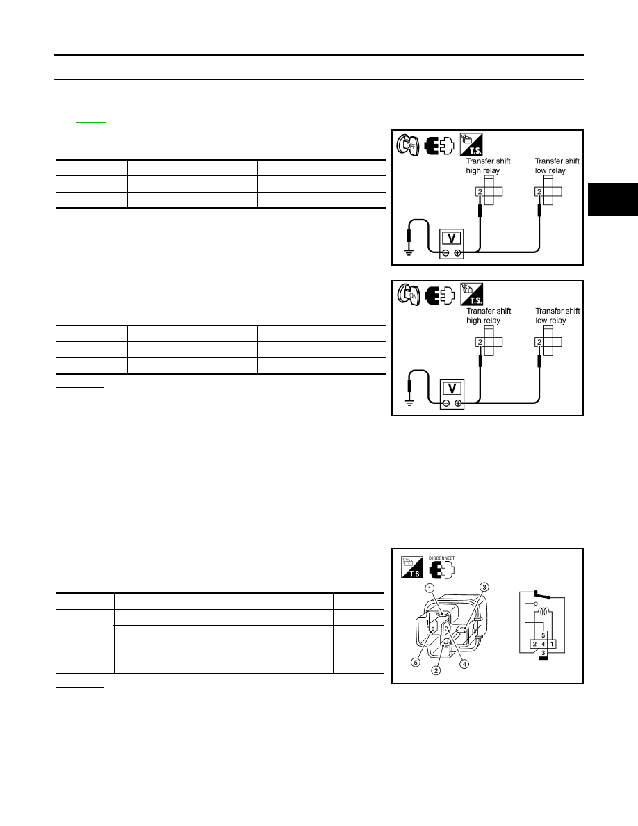
CHECK TRANSFER RELAY
1.
Turn ignition switch “OFF”. (Stay for at least 5 seconds.)
2.
Remove transfer shift high relay and transfer shift low relay.
3.
Apply 12V direct current between transfer shift high and low
relay terminals 1 and 2.
4.
Check continuity between relay terminals 3 and 4, 3 and 5.
OK or NG
OK
>> GO TO 5.
NG
>> Replace the transfer shift high or low relay.
Connector
Terminal
Voltage (Approx.)
E46
2 - Ground
0V
E47
2 - Ground
0V
SDIA3384E
Connector
Terminal
Voltage (Approx.)
E46
2 - Ground
Battery voltage
E47
2 - Ground
Battery voltage
SDIA3385E
Terminal
Condition
Continuity
3 - 4
12V direct current supply between terminals 1 and 2
No
OFF
Yes
3 - 5
12V direct current supply between terminals 1 and 2
Yes
OFF
No
LDIA0099E