Nissan Pathfinder (2007 year). Manual - part 419


  Index      Manuals     Nissan Pathfinder (2007 year) - Service and Repair Manual


Search            copyright infringement  


Content      ..     417      418      419      420     ..


Nissan Pathfinder (2007 year). Manual - part 419


TROUBLE DIAGNOSIS FOR SYSTEM

TF-233

[TX15B]

C

E

F

G

H

I

J

K

L

M

A

B

TF

2007 Pathfinder

4. 

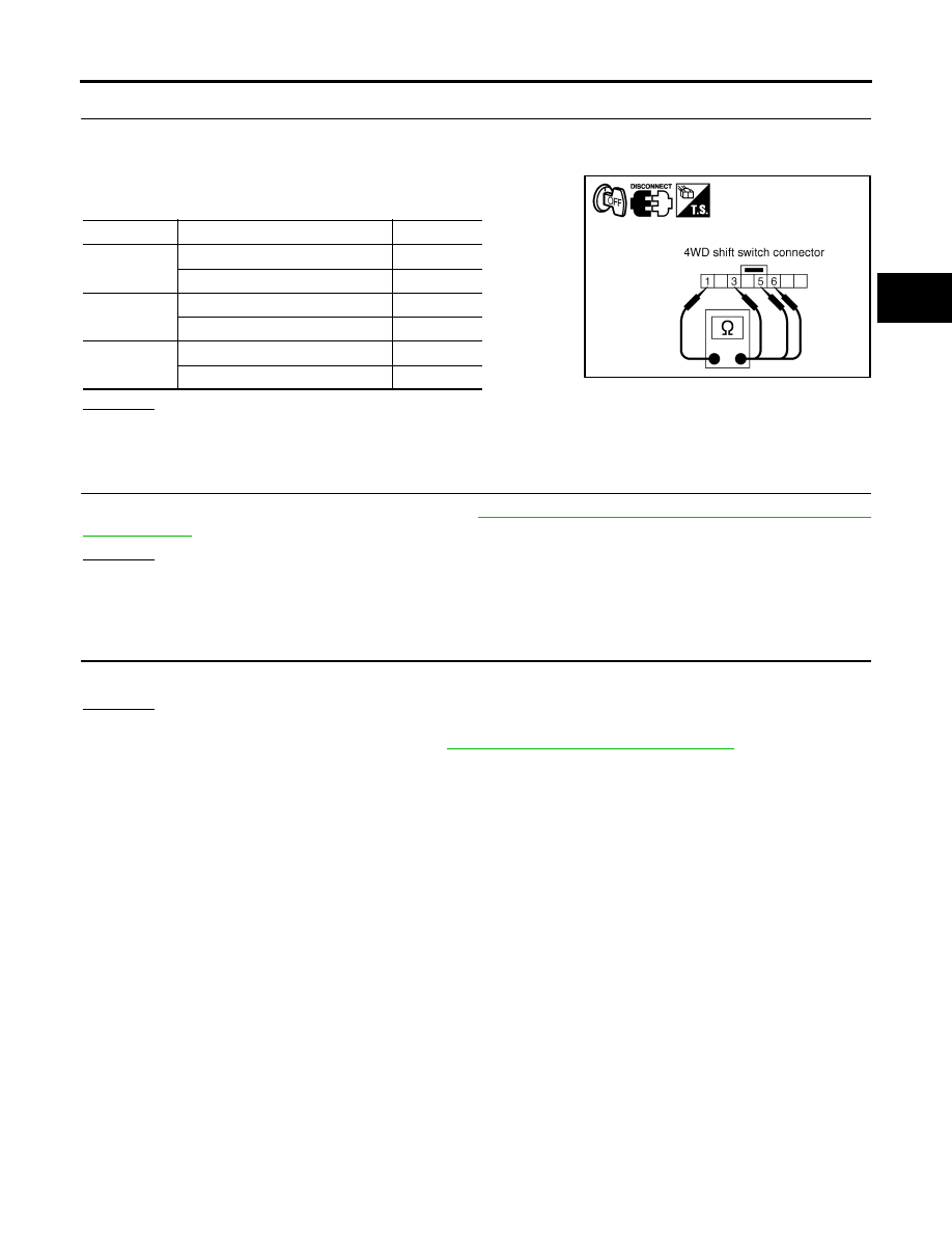
CHECK 4WD SHIFT SWITCH

1.

Turn ignition switch “OFF”.  (Stay for at least 5 seconds.)

2.

Remove 4WD shift switch harness connector.

3.

Operate 4WD shift switch and check continuity between 4WD
shift switch terminals.

OK or NG

OK

>> GO TO 5.

NG

>> Replace 4WD shift switch.

5. 

CHECK TRANSFER CONTROL UNIT

Check transfer control unit input/output signal. Refer to 

TF-211, "Transfer Control Unit Input/Output Signal Ref-

erence Values"

 .

OK or NG

OK

>> GO TO 6.

NG

>> Check transfer control unit pin terminals for damage or loose connection with harness connector.

If any items are damaged, repair or replace damaged parts.

6. 

CHECK DTC

Perform the self-diagnosis, after driving a vehicle for a while.

OK or NG

OK

>> Inspection End.

NG

>> Replace transfer control unit. Refer to 

TF-268, "TRANSFER CONTROL UNIT"

 .

Terminal

Condition

Continuity

1 - 3

4WD shift switch: 2WD

Yes

4WD shift switch: 4H and 4LO

No

1 - 5

4WD shift switch: 4H

Yes

4WD shift switch: 2WD and 4LO

No

1 - 6

4WD shift switch: 4LO

Yes

4WD shift switch: 2WD and 4H

No

SDIA2805E

TF-234

[TX15B]

TROUBLE DIAGNOSIS FOR SYSTEM

2007 Pathfinder

COMPONENT INSPECTION

1.

Turn ignition switch “OFF”.  (Stay for at least 5 seconds.)

2.

Remove 4WD shift switch harness connector. 

3.

Operate 4WD shift switch and check continuity between 4WD
shift switch terminals.

4.

If NG, replace the 4WD shift switch.

Wait Detection Switch

EDS0038G

CONSULT-II REFERENCE VALUE IN DATA MONITOR MODE

Data are reference value.

TRANSFER CONTROL UNIT TERMINALS AND REFERENCE VALUE

Data are reference value and are measured between each terminal and ground.

CAUTION:

When using a circuit tester to measure voltage for inspection, be sure not to extend forcibly any connector terminals.

Terminal

Condition

Continuity

1 - 3

4WD shift switch: 2WD

Yes

4WD shift switch: 4H and 4LO

No

1 - 5

4WD shift switch: 4H

Yes

4WD shift switch: 2WD and 4LO

No

1 - 6

4WD shift switch: 4LO

Yes

4WD shift switch: 2WD and 4H

No

SDIA2805E

Monitored item

Content

Condition

Display value

WAIT DETCT SW [ON/
OFF]

Condition of wait detection 
switch

Vehicle stopped

Engine running

A/T selector lever “N” 
position

Brake pedal depressed

4WD shift switch
: 4H and 4LO

ON

4WD shift switch: 2WD

OFF

Terminal

Wire 

color

Item

Condition

Data (Approx.)

17

O

Wait detection switch

Vehicle stopped

Engine running

A/T selector 
lever “N” position

Brake pedal 
depressed

4WD shift switch: 4H and 4LO

0V

4WD shift switch: 2WD

Battery voltage

TROUBLE DIAGNOSIS FOR SYSTEM

TF-235

[TX15B]

C

E

F

G

H

I

J

K

L

M

A

B

TF

2007 Pathfinder

DIAGNOSTIC PROCEDURE

1. 

CHECK WAIT DETECTION SWITCH SIGNAL

 With CONSULT-II

1.

Start engine.

2.

Select “DATA MONITOR” mode for “ALL MODE AWD/4WD” with CONSULT-II.

3.

Read out the value of “WAIT DETCT SW”.

 Without CONSULT-II

1.

Start engine.

2.

Check voltage between transfer control unit harness connector
terminal and ground.

OK or NG

OK >> GO 

TO 

5.

NG

>> GO TO 2.

2. 

CHECK HARNESS BETWEEN TRANSFER CONTROL UNIT AND WAIT DETECTION SWITCH

1.

Turn ignition switch “OFF”.  (Stay for at least 5 seconds.)

2.

Disconnect transfer control unit harness connector and the wait detection switch harness connector.

3.

Check continuity between transfer control unit harness connec-
tor M152 terminal 17 and wait detection switch harness connec-
tor F59 terminal 10.

Also check harness for short to ground and short to power.

OK or NG

OK

>> GO TO 3.

NG

>> Repair or replace damaged parts.

Condition

Display value

Vehicle stopped

Engine running

A/T selector lever “N” position

Brake pedal depressed

4WD shift switch: 4H and 4LO

ON

4WD shift switch: 2WD

OFF

PDIA0221E

Connector

Terminal

Condition

Voltage 

(Approx.)

E142

17 - 

Ground

Vehicle stopped

Engine running

A/T selector lever 
“N” position

Brake pedal 
depressed

4WD shift switch
: 4H and 4LO

0V

4WD shift switch: 2WD

Battery 
voltage

SDIA3367E

Continuity should exist.

SDIA3368E

TF-236

[TX15B]

TROUBLE DIAGNOSIS FOR SYSTEM

2007 Pathfinder

3. 

CHECK GROUND CIRCUIT

1.

Turn ignition switch “OFF”.  (Stay for at least 5 seconds.)

2.

Disconnect wait detection switch harness connector.

3.

Check continuity between wait detection switch harness con-
nector F59 terminal 11 and ground.

Also check harness for short to power.

 OK or NG

 OK 

>> GO TO 4.

 NG

>> Repair open circuit or short to power in harness or con-

nectors.

4. 

CHECK WAIT DETECTION SWITCH 

1.

Turn ignition switch “OFF”.  (Stay for at least 5 seconds.)

2.

Disconnect wait detection switch harness connector.

3.

Remove wait detection switch. Refer to 

TF-202, "Location of Electrical Parts"

 .

4.

Push and release wait detection switch and check continuity
between wait detection switch terminals 10 and 11.

OK or NG

OK

>> GO TO 5.

NG

>> Replace wait detection switch.  Refer to 

TF-202, "Loca-

tion of Electrical Parts"

 .

5. 

CHECK TRANSFER CONTROL UNIT

Check transfer control unit input/output signal. Refer to 

TF-211, "Transfer Control Unit Input/Output Signal Ref-

erence Values"

 .

OK or NG

OK

>> GO TO 6.

NG

>> Check transfer control unit pin terminals for damage or loose connection with harness connector.

If any items are damaged, repair or replace damaged parts.

6. 

CHECK DTC

Perform the self-diagnosis, after driving a vehicle for a while.

OK or NG

OK

>> Inspection End.

NG

>> Replace transfer control unit. Refer to 

TF-268, "Removal and Installation"

 .

Continuity should exist.

PDIA0207E

Terminal

Condition

Continuity

10 - 11

Push wait detection switch

Yes

Release wait detection switch

No

PDIA0208E

TROUBLE DIAGNOSIS FOR SYSTEM

TF-237

[TX15B]

C

E

F

G

H

I

J

K

L

M

A

B

TF

2007 Pathfinder

COMPONENT INSPECTION

1.

Turn ignition switch “OFF”.  (Stay for at least 5 seconds.)

2.

Disconnect wait detection switch harness connector.

3.

Remove wait detection switch.  Refer to 

TF-202, "Location of Electrical Parts"

 .

4.

Push and release wait detection switch and check continuity
between wait detection switch terminals 10 and 11.

5.

If NG, replace the wait detection switch.  Refer to 

TF-202, "Loca-

tion of Electrical Parts"

 .

PNP Switch Signal

EDS0038H

DIAGNOSTIC PROCEDURE

1. 

CHECK DTC WITH TCM

Perform self-diagnosis with TCM. Refer to 

AT-88, "CONSULT-II START PROCEDURE"

 .

Is any malfunction detected by self-diagnosis?

YES

>> Check the malfunctioning system.

NO

>> GO TO 2.

2. 

CHECK TRANSFER CONTROL UNIT

Check transfer control unit input/output signal. Refer to 

TF-211, "Transfer Control Unit Input/Output Signal Ref-

erence Values"

 .

OK or NG

OK

>> GO TO 3.

NG

>> Check transfer control unit pin terminals for damage or loose connection with harness connector.

If any items are damaged, repair or replace damaged parts.

3. 

CHECK DTC

Perform the self-diagnosis, after driving a vehicle for a while.

OK or NG

OK

>> Inspection End.

NG

>> Perform self-diagnosis with TCM again. Refer to 

AT-88, "CONSULT-II START PROCEDURE"

 .

Terminal

Condition

Continuity

10 - 11

Push wait detection switch

Yes

Release wait detection switch

No

PDIA0208E

TF-238

[TX15B]

TROUBLE DIAGNOSIS FOR SYSTEM

2007 Pathfinder

Actuator Motor

EDS0038I

CONSULT-II REFERENCE VALUE IN DATA MONITOR MODE

Data are reference value.

TRANSFER CONTROL UNIT TERMINALS AND REFERENCE VALUE

Data are reference value and are measured between each terminal and ground.

CAUTION:

When using a circuit tester to measure voltage for inspection, be sure not to extend forcibly any connector terminals.

Monitored item

Content

Condition

Display value

SHIFT ACT 1 [ON/OFF]

Output condition to actua-
tor motor (clockwise)

Vehicle stopped

Engine running

A/T selector lever “N” 
position

Brake pedal depressed

4WD shift switch
: 2WD to 4H or 4H to 4LO 
or 2WD to 4LO

ON

Except the above

OFF

SHIFT AC MON1 [ON/
OFF]

Check signal for transfer 
control unit signal output

Vehicle stopped

Engine running

A/T selector lever “N” 
position

Brake pedal depressed

4WD shift switch
: 2WD to 4H or 4H to 4LO 
or 2WD to 4LO

ON

Except the above

OFF

SHIFT ACT 2 [ON/OFF]

Output condition to actua-
tor motor (counterclock-
wise)

Vehicle stopped

Engine running

A/T selector lever “N” 
position

Brake pedal depressed

4WD shift switch
: 4LO to 4H or 4H to 2WD 
or 4LO to 2WD

ON

Except the above

OFF

SHIFT AC MON2 [ON/
OFF]

Check signal for transfer 
control unit signal output

Vehicle stopped

Engine running

A/T selector lever “N” 
position

Brake pedal depressed

4WD shift switch
: 4LO to 4H or 4H to 2WD 
or 4LO to 2WD

ON

Except the above

OFF

Terminal

Wire 

color

Item

Condition

Data (Approx.)

27

L

Actuator motor power supply

Ignition switch: ON

Battery voltage

Ignition switch: OFF (5 seconds after ignition switch is turned 
OFF)

0V

28

SB

Actuator motor (+)

Vehicle stopped

Engine running

A/T selector 
lever “N” position

Brake pedal 
depressed

When 4WD shift switch is operated (while 
actuator motor is operating)

Battery voltage

When 4WD shift switch is not operated

0V

31

G

Actuator motor (-)

Always

0V

42

LG

Transfer shift high relay

Vehicle stopped

Engine running

A/T selector 
lever “N” position

Brake pedal 
depressed

4WD shift switch: 2WD to 4H or 4H to 4LO 
or 2WD to 4LO

0V

Except the above

Battery voltage

47

O

Transfer shift high relay moni-
tor

4WD shift switch: 2WD to 4H or 4H to 4LO 
or 2WD to 4LO

Battery volt-
age 

 0V

Except the above

0V

48

R

Transfer shift low relay moni-
tor

4WD shift switch: 4LO to 4H or 4H to 2WD 
or 4LO to 2WD

Battery volt-
age 

 0V

Except the above

0V

50

Y

Transfer shift low relay

4WD shift switch: 4LO to 4H or 4H to 2WD 
or 4LO to 2WD

0V

Except the above

Battery voltage

TROUBLE DIAGNOSIS FOR SYSTEM

TF-239

[TX15B]

C

E

F

G

H

I

J

K

L

M

A

B

TF

2007 Pathfinder

DIAGNOSTIC PROCEDURE

1. 

CHECK ACTUATOR MOTOR SIGNAL

 With CONSULT-II

1.

Start engine.

2.

Select “DATA MONITOR” mode for “ALL MODE AWD/4WD” with CONSULT-II.

3.

Read out the value of “SHIFT ACT1”, “SHIFT AC MON1”,
“SHIFT ACT2”, “SHIFT AC MON2”.

 Without CONSULT-II

1.

Start engine.

2.

Depress brake pedal and stop vehicle.

3.

Set A/T selector lever to "N" position.

4.

Check voltage between transfer control unit harness connector
terminal and ground.

Monitored item

Condition

Display value

SHIFT ACT1

Vehicle 
stopped

Engine run-
ning

A/T selector 
lever “N” 
position

Brake pedal 
depressed

4WD shift switch: 2WD to 
4H or 4H to 4LO or 2WD to 
4LO

ON

Except the above

OFF

SHIFT AC MON1

4WD shift switch: 2WD to 
4H or 4H to 4LO or 2WD to 
4LO

ON

Except the above

OFF

SHIFT ACT2

4WD shift switch: 4LO to 
4H or 4H to 2WD or 4LO to 
2WD

ON

Except the above

OFF

SHIFT AC MON2

4WD shift switch: 4LO to 
4H or 4H to 2WD or 4LO to 
2WD

ON

Except the above

OFF

Connector

Terminal

Condition

Voltage 

(Approx.)

M153

28 - 

Ground

When 4WD shift switch is operated (While 
actuator motor is operating.)

Battery 
voltage 


0V

When 4WD shift switch is not operated

0V

31 - 

Ground

Always

0V

42 - 

Ground

Vehicle 
stopped

Engine run-
ning

A/T selector 
lever “N” 
position

Brake pedal 
depressed

4WD shift switch: 2WD to 
4H or 4H to 4LO or 2WD 
to 4LO

0V

Except the above

Battery 
voltage

PDIA0223E

WDIA0144E

TF-240

[TX15B]

TROUBLE DIAGNOSIS FOR SYSTEM

2007 Pathfinder

OK or NG

OK 

>> GO TO 9.

NG

>> GO TO 2.

2. 

CHECK ACTUATOR MOTOR POWER SUPPLY CIRCUIT

1.

Turn ignition switch “OFF”.  (Stay for at least 5 seconds.)

2.

Disconnect transfer control unit harness connector.

3.

Check voltage between transfer control unit harness connector
terminal 27 and ground.

4.

Turn ignition switch “ON”.

5.

Check voltage between transfer control unit harness connector
terminal 27 and ground.

OK or NG

OK

>> GO TO 3.

NG

>> 1. Check harness for short or open between transfer

control unit harness connector M153 terminal 27 and
transfer shut off relay 2 harness connector E157 ter-
minal 5  and 10A fuse (No. 57, located in the fuse and relay block).  If any items are damaged,
repair or replace damaged parts.

2. Perform trouble diagnosis for power supply circuit.  Refer to 

TF-222, "Power Supply Circuit For

Transfer Control Unit"

 .

M153

 47 - 

Ground

Vehicle 
stopped

Engine run-
ning

A/T selector 
lever “N” 
position

Brake pedal 
depressed

4WD shift switch: 2WD to 
4H or 4H to 4LO or 2WD 
to 4LO

Battery 
voltage 


0V

Except the above

0V

 48 - 

Ground

4WD shift switch: 4LO to 
4H or 4H to 2WD or 4LO 
to 2WD

Battery 
voltage 


0V

Except the above

0V

 50 - 

Ground

4WD shift switch: 4LO to 
4H or 4H to 2WD or 4LO 
to 2WD

0V

Except the above

Battery 
voltage

Connector

Terminal

Condition

Voltage 

(Approx.)

Connector

Terminal

Voltage (Approx.)

M153

27 - Ground

0V

SDIA2808E

Connector

Terminal

Voltage (Approx.)

M153

27 - Ground

Battery voltage

SDIA2807E


Content      ..     417      418      419      420     ..