Nissan Pathfinder (2007 year). Manual - part 418
TROUBLE DIAGNOSIS FOR SYSTEM
TF-225
[TX15B]
C
E
F
G
H
I
J
K
L
M
A
B
TF
2007 Pathfinder
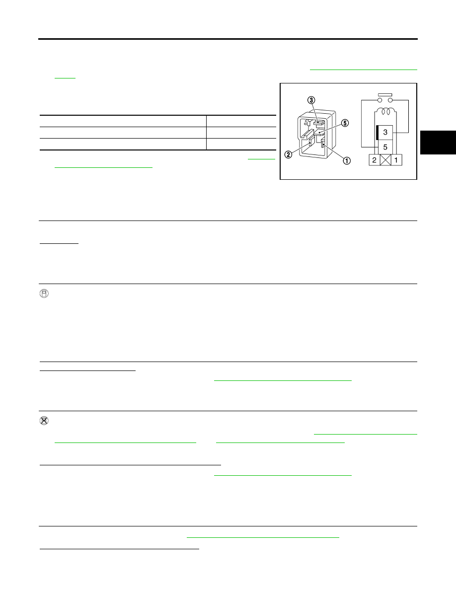
COMPONENT INSPECTION
1.
Turn ignition switch “OFF”. (Stay for at least 5 seconds.)
2.
Remove transfer shut off relay 1 and transfer shut off relay 2. Refer to
TF-202, "Location of Electrical
3.
Apply 12V direct current between transfer shut off relay termi-
nals 1 and 2.
4.
Check continuity between relay terminals 3 and 5.
5.
If NG, replace the transfer shut off relay 1 or 2. Refer to
"Location of Electrical Parts"
.
Transfer Control Unit
EDS0038B
DIAGNOSTIC PROCEDURE
1.
INSPECTION START
Do you have CONSULT-II?
YES or NO
YES
>> GO TO 2.
NO
>> GO TO 3.
2.
PERFORM SELF-DIAGNOSIS (WITH CONSULT-II)
With CONSULT-II
1.
Turn ignition switch “ON”. (Do not start engine.)
2.
Select “SELF-DIAG RESULTS” mode for “ALL MODE AWD/4WD” with CONSULT-II.
3.
Touch “ERASE”.
4.
Turn ignition switch “OFF” and wait at least 10 seconds.
5.
Perform the self-diagnosis again.
Is the “CONTROL UNIT 1 [P1802]”, “CONTROL UNIT 2 [P1803]”, “CONTROL UNIT 3 [P1804]” or “CONTROL
UNIT 4 [P1809]” displayed?
YES
>> Replace transfer control unit. Refer to
TF-268, "TRANSFER CONTROL UNIT"
NO
>> Inspection End.
3.
PERFORM SELF-DIAGNOSIS (WITHOUT CONSULT-II)
Without CONSULT-II
1.
Perform the self-diagnosis and then erase self-diagnostic results. Refer to
PROCEDURE (WITHOUT CONSULT-II)"
TF-221, "ERASE SELF-DIAGNOSIS"
2.
Perform the self-diagnosis again.
Do the self-diagnostic results indicate AD converter?
YES
>> Replace transfer control unit. Refer to
TF-268, "TRANSFER CONTROL UNIT"
NO
>> Inspection End.
Output Shaft Revolution Signal (TCM)
EDS0038C
DIAGNOSTIC PROCEDURE
1.
CHECK DTC WITH TCM
Perform self-diagnosis with TCM. Refer to
AT-88, "CONSULT-II START PROCEDURE"
Is any malfunction detected by self-diagnosis?
YES
>> Check the malfunctioning system.
NO
>> GO TO 2.
Condition
Continuity
12V direct current supply between terminals 1 and 2
Yes
OFF
No
SCIA1245E