Nissan Pathfinder (2007 year). Manual - part 408


  Index      Manuals     Nissan Pathfinder (2007 year) - Service and Repair Manual


Search            copyright infringement  


Content      ..     406      407      408      409     ..


Nissan Pathfinder (2007 year). Manual - part 408


TRANSFER ASSEMBLY

TF-145

[ATX14B]

C

E

F

G

H

I

J

K

L

M

A

B

TF

2007 Pathfinder

TRANSFER ASSEMBLY

PFP:33100

Removal and Installation

EDS0037J

REMOVAL

1.

Set transfer state as 2WD when 4WD shift switch is at 2WD.

2.

Remove the undercovers using power tool.

3.

Drain the transfer fluid. Refer to 

TF-13, "DRAINING"

 .

4.

Remove the center exhaust tube and main muffler. Refer to 

EX-3, "Removal and Installation"

 .

5.

Remove the front and rear propeller shafts. Refer to 

PR-5, "REMOVAL"

  (front), 

PR-10, "REMOVAL"

(rear).

CAUTION:

Do not damage spline, sleeve yoke and rear oil seal when removing rear propeller shaft.

NOTE:
Insert a plug into the rear oil seal after removing the rear propeller shaft.

6.

Remove the A/T nuts from the A/T crossmember. Refer to 

AT-243, "COMPONENTS"

 .

7.

Position two suitable jacks under the A/T and transfer assembly.

8.

Remove the crossmember. Refer to 

AT-243, "COMPONENTS"

 .

WARNING:

Support A/T and transfer assembly using two suitable jacks while removing crossmember.

9.

Disconnect the electrical connectors from the following:

ATP switch

Neutral 4LO switch

Wait detection switch

Transfer motor

Transfer control device

Transfer terminal cord assembly

10. Disconnect each air breather hose from the following. Refer to 

TF-139, "Removal and Installation"

 .

Actuator

Breather tube (transfer)

Transfer motor

11. Remove the transfer control device from the extension housing.

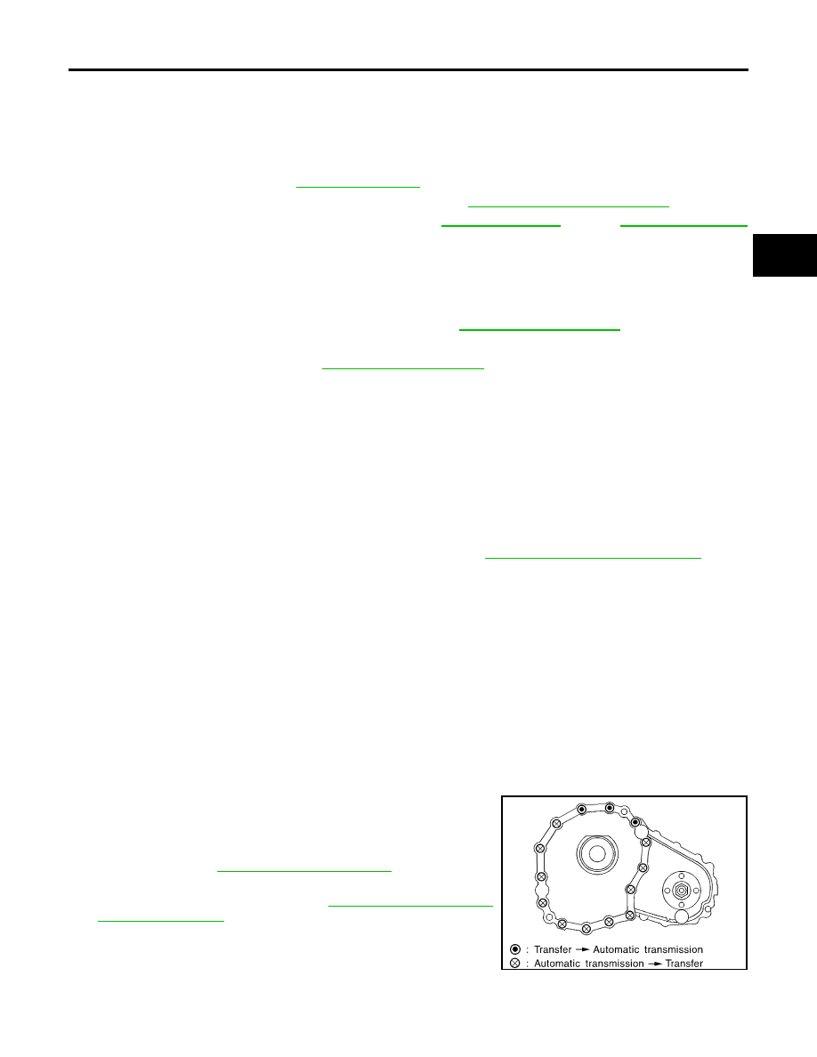
12. Remove the transfer to A/T and A/T to transfer bolts.

13. Remove the transfer assembly.

WARNING:

Support transfer assembly with suitable jack while removing it.

CAUTION:

Do not damage rear oil seal (A/T).

INSTALLATION

Installation is in the reverse order of removal.

Tighten the bolts to specification.

Fill the transfer with new fluid and check for fluid leakage and
fluid level. Refer to 

TF-13, "TRANSFER FLUID"

 .

Start the engine for one minute. Then stop the engine and
recheck the transfer fluid. Refer to 

TF-13, "FLUID LEAKAGE

AND FLUID LEVEL"

 .

Transfer bolt torque

: 36 N·m (3.7 kg-m, 27 ft-lb)

SMT872C

TF-146

[ATX14B]

TRANSFER ASSEMBLY

2007 Pathfinder

Disassembly and Assembly

EDS0037K

COMPONENTS

1.

2-4 sleeve

2.

L-H sleeve

3.

Snap ring

4.

Internal gear

5.

Planetary carrier assembly

6.

Metal bushing

7.

Needle bearing

8.

Sun gear

9.

Carrier bearing

10.

Snap ring

11.

Snap ring

12.

Input bearing

13.

Wait detection switch

14.

Check plug

15.

Check spring

16.

Check ball

17.

Front case

18.

Snap ring

19.

Input oil seal

20.

Shift cross

21.

Side oil seal

22.

Lock pin

23.

Shift lever

24.

Gasket

25.

Drain plug

26.

Front oil seal

27.

Companion flange

28.

Self-lock nut

29.

Mainshaft

30.

Needle bearing

31.

Front bearing

32.

Front drive shaft

33.

Rear bearing

34.

Spacer

35.

Drive chain

36.

Clutch drum

37.

Snap ring

38.

Clutch hub 

39.

Snap ring

40.

Retaining plate

41.

Driven plate (10 sheet)

42.

Drive plate (10 sheet)

43.

Return spring assembly

44.

Press flange

45.

Thrust needle bearing

46.

Snap ring

47.

Retaining pin

48.

L-H fork

WDIA0194E

TRANSFER ASSEMBLY

TF-147

[ATX14B]

C

E

F

G

H

I

J

K

L

M

A

B

TF

2007 Pathfinder

49.

2-4 fork

50.

Shift fork spring

51.

Fork guide

52.

Retainer pin

53.

Shift rod

1.

Dust cover

2.

Rear oil seal

3.

Rear case

4.

Breather tube

5.

Seal ring

6.

Main oil pump cover

7.

Inner gear

8.

Outer gear

9.

Main oil pump housing

10.

D-ring

11.

D-ring

12.

Clutch piston

13.

Thrust needle bearing race

14. Oil strainer

15.

O-ring

16.

Snap ring

17. Control valve assembly

18.

Lip seal (large 5 pieces)

19.

Lip seal (small 2 pieces)

20. Gasket

21.

Filler plug

22.

Oil filter stud

23. O-ring

24.

Oil filter

25

ATP switch

26. Neutral-4LO switch

27.

Oil pressure check plug

28.

Harness bracket

29. Air breather hose clamp

30.

Stem bleeder

31.

Harness bracket

32. Center case

33.

Mainshaft rear bearing

34.

C-ring

35. Washer holder

36.

Snap ring

37.

Sub oil pump housing

38. Outer gear

39.

Inner gear

WDIA0302E

TF-148

[ATX14B]

TRANSFER ASSEMBLY

2007 Pathfinder

DISASSEMBLY
Rear Case

1.

Remove the rear case bolts.

2.

Remove the rear case from the center case.

3.

Remove the dust cover using suitable tool.

4.

Remove the rear oil seal using suitable tool.

CAUTION:

Do not damage rear case.

5.

Remove the breather tube.

40.

Sub oil pump cover

41. O-ring

42.

Transfer motor

43.

Connector bracket

A.

Apply Genuine Anaerobic Liquid 
Gasket, Three Bond TB1133C or 
equivalent.

B.

Apply Genuine Liquid Gasket, 
Three Bond TB1215 or equivalent.

SDIA2092E

SDIA2093E

SDIA2094E

SDIA2095E

TRANSFER ASSEMBLY

TF-149

[ATX14B]

C

E

F

G

H

I

J

K

L

M

A

B

TF

2007 Pathfinder

Front Case

1.

Remove the rear case assembly. Refer to 

TF-148, "Rear Case"

 .

2.

Remove the lock pin nut.

3.

Remove the lock pin using suitable tool.

4.

Remove the shift lever.

5.

Remove the side oil seal from the front case using suitable tool.

CAUTION:

Do not damage front case or shift cross.

6.

Remove the check plug, check spring and check ball.

7.

Remove the wait detection switch.

8.

Remove the self-lock nut from the companion flange using Tool.

SDIA2150E

SDIA2166E

WDIA0196E

Tool number

: KV40104000 (

)

SDIA2841E

TF-150

[ATX14B]

TRANSFER ASSEMBLY

2007 Pathfinder

9.

Put a matching mark on top of the front drive shaft thread in line
with the mark on the companion flange.

CAUTION:

Use paint to make the matching mark on the front drive
shaft thread. Never damage the front drive shaft.

10. Remove the companion flange using suitable tool.

11. Remove the center case bolts, harness bracket and air breather.

12. Remove the filler plug and gasket.

13. Separate the center case from the front case. Then remove the

center case from the front case by prying it up using suitable
tool.

CAUTION:

Do not damage the mating surfaces.

14. Remove the shift rod components together with the 2-4 sleeve

and L-H sleeve.

15. Remove the shift cross from the front case.

SDIA2779E

WDIA0133E

SDIA2100E

SDIA2101E

SDIA2140E

TRANSFER ASSEMBLY

TF-151

[ATX14B]

C

E

F

G

H

I

J

K

L

M

A

B

TF

2007 Pathfinder

16. Remove the 2-4 sleeve and L-H sleeve from the 2-4 fork and L-

H fork respectively.

17. Drive out the retaining pin from the shift rod using suitable tool.

18. Remove the L-H fork, 2-4 fork, shift fork spring and fork guide

from the shift rod.

19. Remove the input oil seal from the front case using suitable tool.

CAUTION:

Do not damage front case or sun gear.

20. Remove the snap ring from the sun gear.

CAUTION:

Do not damage front case or sun gear.

SMT992C

WDIA0134E

SDIA2142E

SDIA3382E

SDIA2144E

TF-152

[ATX14B]

TRANSFER ASSEMBLY

2007 Pathfinder

21. Remove the sun gear assembly and planetary carrier assembly

from the front case using Tool.

22. Remove the snap ring and internal gear using suitable tool.

23. Remove the front oil seal using suitable tool.

CAUTION:

Do not damage front case.

24. Remove the snap ring from the front case.

25. Remove the input bearing from the front case using Tool.

Tool number

: ST35300000 (

)

SDIA2145E

SMT004D

SDIA2170E

SDIA2171E

Tool number

: ST33200000 (J-26082)

SDIA2178E


Content      ..     406      407      408      409     ..