Nissan Pathfinder (2007 year). Manual - part 361


  Index      Manuals     Nissan Pathfinder (2007 year) - Service and Repair Manual


Search            copyright infringement  


Content      ..     359      360      361      362     ..


Nissan Pathfinder (2007 year). Manual - part 361


REAR FINAL DRIVE ASSEMBLY

RFD-37

C

E

F

G

H

I

J

K

L

M

A

B

RFD

2007 Pathfinder

2.

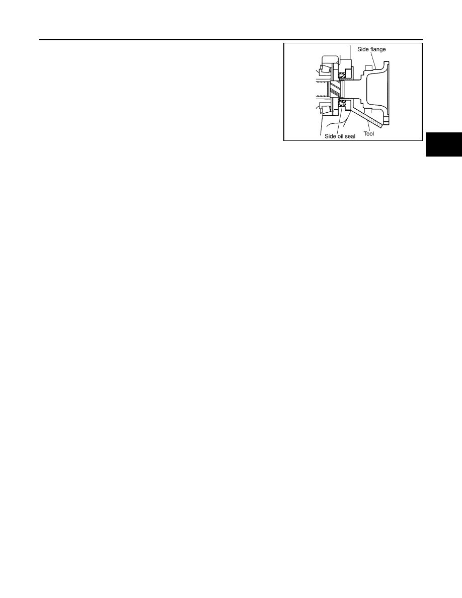
Install the side flange using Tool.

a.

Install the Tool to the side oil seal as shown.

b.

Insert the side flange until the serrated part of the side flange
has engaged the serrated part of the side gear and remove the
Tool.

c.

Drive in the side flange using suitable tool.

NOTE:
Installation is completed when the driving sound of the side
flange turns into a sound which seems to affect the whole rear
final drive assembly.

Tool number

: KV38107900 (J-39352)

SDIA0822E

RFD-38

SERVICE DATA AND SPECIFICATIONS (SDS)

2007 Pathfinder

SERVICE DATA AND SPECIFICATIONS (SDS)

PFP:00030

General Specifications

EDS003A5

Inspection and Adjustment

EDS003A6

DRIVE GEAR RUNOUT

Unit: mm (in)

SIDE GEAR CLEARANCE

Unit: mm (in)

PRELOAD TORQUE

BACKLASH

Unit: mm (in)

COMPANION FLANGE RUNOUT

Unit: mm (in)

SELECTIVE PARTS
Side Gear Thrust Washer

Unit: mm (in)

*: Always check with the Parts Department for the latest parts information.

Applied model

VQ40DE

2WD

4WD

Final drive model

R200

Gear ratio

3.133

3.357

Number of teeth (Drive gear/Drive pinion)

47/15

47/14

Oil capacity (Approx.)

1.4 

 (3 US pt, 2-1/2 lmp pt)

Number of pinion gears

2

Drive pinion adjustment spacer type

Collapsible

Item

Runout limit

Drive gear back face

 0.05 (0.0020) or less

Item

Specification

Side gear back clearance
(Clearance between side gear and differential case for adjusting 
side gear backlash)

0.2 (0.008) or less

(Each gear should rotate smoothly without excessive resistance 

during differential motion.)

Item

Specification

Drive pinion bearing preload torque

2.65 - 3.23 N·m (0.27 - 0.32 kg

m, 24 - 28 in-lb)

Side bearing preload torque (reference value determined by drive 
gear bolt pulling force)

0.20 - 0.52 N·m (0.02 - 0.05 kg

m, 2 - 4 in-lb)

Drive gear bolt pulling force (by spring gauge)

34.2 

 39.2 N (3.5 

 4 kg, 7.7 

 8.8 lb)

Total preload torque
(Total preload torque = drive pinion bearing preload torque + Side 
bearing preload torque)

2.84 - 3.75 N·m (0.29 - 0.38 kg

m, 26 - 33 in-lb)

Item

Specification

Drive gear to drive pinion gear

0.10 - 0.15 (0.0039 - 0.0059)

Item

Runout limit

Outer side of the companion flange

 0.08 (0.0031) or less

Thickness Part 

number*

Thickness Part 

number*

0.75 (0.0295)
0.78 (0.0307)
0.81 (0.0319)
0.84 (0.0331)

38424 0C000
38424 0C001
38424 0C002
38424 0C003

0.87 (0.0343)
0.90 (0.0350)
0.93 (0.0366)

38424 0C004
38424 0C005
38424 0C006

SERVICE DATA AND SPECIFICATIONS (SDS)

RFD-39

C

E

F

G

H

I

J

K

L

M

A

B

RFD

2007 Pathfinder

Drive Pinion Height Adjusting Washer

Unit: mm (in)

*: Always check with the Parts Department for the latest parts information.

Side Bearing Adjusting Washer

Unit: mm (in)

*: Always check with the Parts Department for the latest parts information.

Thickness 

Part number*

Thickness 

Part number*

3.05 (0.1201)
3.08 (0.1213)

3.11 (0.1224)

3.14 (0.1236)

38154 0C000
38154 0C001
38154 0C002
38154 0C003

3.17 (0.1248)
3.20 (0.1260)
3.23 (0.1272)
3.26 (0.1283)

38154 0C004
38154 0C005
38154 0C006
38154 0C007

Thickness

Part number*

Thickness

Part number*

2.00 (0.0787)
2.05 (0.0807)
2.10 (0.0827)
2.15 (0.0846)
2.20 (0.0866)
2.25 (0.0886)
2.30 (0.0906)

38453 N3100
38453 N3101
38453 N3102
38453 N3103
38453 N3104
38453 N3105
38453 N3106

2.35 (0.0925)
2.40 (0.0945)
2.45 (0.0965)
2.50 (0.0984)
2.55 (0.1004)
2.60 (0.1024)
2.65 (0.1043)

38453 N3107
38453 N3108
38453 N3109
38453 N3110

38453 N3111
38453 N3112
38453 N3113

RFD-40

SERVICE DATA AND SPECIFICATIONS (SDS)

2007 Pathfinder

RSU-1

REAR SUSPENSION

E  SUSPENSION

CONTENTS

C

D

F

G

H

I

J

K

L

M

SECTION 

RSU

A

B

RSU

2007 Pathfinder

PRECAUTIONS .......................................................... 2

Precautions for Supplemental Restraint System 
(SRS) “AIR BAG” and “SEAT BELT PRE-TEN-
SIONER” .................................................................. 2
Precautions for Rear Suspension  ............................ 2

PREPARATION ........................................................... 3

Commercial Service Tools ........................................ 3

NOISE, VIBRATION, AND HARSHNESS (NVH) 
TROUBLESHOOTING ................................................ 4

NVH Troubleshooting Chart  ..................................... 4

REAR SUSPENSION ASSEMBLY  ............................. 5

Components ............................................................. 5
On-Vehicle Inspection  .............................................. 5
Wheel Alignment Inspection ..................................... 6

PRELIMINARY INSPECTION  ............................... 6
GENERAL INFORMATION AND RECOMMEN-
DATIONS .............................................................. 6
THE ALIGNMENT PROCESS  .............................. 7
CAMBER ............................................................... 7
TOE-IN .................................................................. 7

REAR SUSPENSION MEMBER ................................. 9

Removal and Installation  .......................................... 9

COMPONENTS .................................................... 9
REMOVAL ............................................................. 9
INSPECTION AFTER REMOVAL  ........................11
INSTALLATION ................................................... 12

SHOCK ABSORBER ................................................ 13

Removal and Installation  ........................................ 13

REMOVAL ........................................................... 13
INSTALLATION ................................................... 13

Inspection ............................................................... 13

SUSPENSION ARM .................................................. 14

Removal and Installation  ........................................ 14

REMOVAL ........................................................... 14
INSPECTION AFTER REMOVAL  ....................... 15
INSTALLATION ................................................... 15

FRONT LOWER LINK  .............................................. 16

Removal and Installation  ........................................ 16

REMOVAL ........................................................... 16
INSPECTION AFTER REMOVAL  ....................... 17
INSTALLATION ................................................... 17

REAR LOWER LINK & COIL SPRING ..................... 18

Removal and Installation  ........................................ 18

REMOVAL ........................................................... 18
INSPECTION AFTER REMOVAL  ....................... 18
INSTALLATION ................................................... 19

STABILIZER BAR  ..................................................... 20

Removal and Installation  ........................................ 20

REMOVAL ........................................................... 20
INSPECTION AFTER REMOVAL  ....................... 20
INSTALLATION ................................................... 20

SERVICE DATA AND SPECIFICATIONS (SDS)  ...... 21

Wheel Alignment  .................................................... 21
Ball Joint  ................................................................. 22
Wheelarch Height (Unladen* ) ................................ 22

RSU-2

PRECAUTIONS

2007 Pathfinder

PRECAUTIONS

PFP:00001

Precautions for Supplemental Restraint System (SRS) “AIR BAG” and “SEAT 
BELT PRE-TENSIONER”

EES002BM

The Supplemental Restraint System such as “AIR BAG” and “SEAT BELT PRE-TENSIONER”, used along
with a front seat belt, helps to reduce the risk or severity of injury to the driver and front passenger for certain
types of collision. This system includes seat belt switch inputs and dual stage front air bag modules. The SRS
system uses the seat belt switches to determine the front air bag deployment, and may only deploy one front
air bag, depending on the severity of a collision and whether the front occupants are belted or unbelted.
Information necessary to service the system safely is included in the SRS and SB section of this Service Man-
ual.

WARNING:

To avoid rendering the SRS inoperative, which could increase the risk of personal injury or death
in the event of a collision which would result in air bag inflation, all maintenance must be per-
formed by an authorized NISSAN/INFINITI dealer.

Improper maintenance, including incorrect removal and installation of the SRS, can lead to per-
sonal injury caused by unintentional activation of the system. For removal of Spiral Cable and Air
Bag Module, see the SRS section.

Do not use electrical test equipment on any circuit related to the SRS unless instructed to in this
Service Manual. SRS wiring harnesses can be identified by yellow and/or orange harnesses or
harness connectors.

Precautions for Rear Suspension

EES00238

When installing the rubber bushings, the final tightening must be done under unladen condition and with
the tires on level ground. Oil will shorten the life of the rubber bushings, so wipe off any spilled oil immedi-
ately.

Unladen condition means the fuel tank, engine coolant and lubricants are at the full specification. The
spare tire, jack, hand tools, and mats are in their designated positions. There are no passengers in the
vehicle.

After installing suspension components, check the wheel alignment.

Caulking nuts are not reusable. Always use new caulking nuts for installation. New caulking nuts are pre-
oiled, do not apply any additional lubrication.

PREPARATION

RSU-3

C

D

F

G

H

I

J

K

L

M

A

B

RSU

2007 Pathfinder

PREPARATION

PFP:00002

Commercial Service Tools

EES00239

Tool name

Description

Power tool

Removing bolts and nuts

PBIC0190E

RSU-4

NOISE, VIBRATION, AND HARSHNESS (NVH) TROUBLESHOOTING

2007 Pathfinder

NOISE, VIBRATION, AND HARSHNESS (NVH) TROUBLESHOOTING

PFP:00003

NVH Troubleshooting Chart

EES0023A

Use chart below to help you find the cause of the symptom. If necessary, repair or replace these parts.

×

: Applicable

Reference page

RS

U-

5

RS

U-

1

3

RS

U-

5

RS

U-

5

RS

U-

2

2

RS

U-

5

RS

U-

6

RS

U-

2

0

PR

-3

, "

N

V

H

 T

rou

bl

e

s

ho

ot

in

g C

h

a

rt

"

RFD

-7

, "

N

V

H

 T

ro

ubl

e

s

h

oot

ing 

C

h

ar

t"

FSU

-4

, "

N

V

H

 T

ro

ubl

e

s

h

oot

ing 

C

h

ar

t"

FA

X

-4

, "

N

V

H

 T

rou

bl

e

s

h

oot

ing 

C

h

a

rt

"

WT

-4

, "

N

V

H

 T

rou

bl

e

s

ho

ot

ing C

h

a

rt

"

WT

-4

, "

N

V

H

 T

rou

bl

e

s

ho

ot

ing C

h

a

rt

"

RA

X-

4

, "

N

V

H

 T

ro

ubl

e

s

h

oot

ing 

C

h

ar

t"

PS

-5

, "

N

V

H

 T

rou

bl

e

s

ho

ot

in

g C

h

a

rt

"

BR

-5

, "

N

V

H

 T

rou

bl

e

s

ho

ot

in

g C

h

a

rt

"

Possible cause and SUSPECTED PARTS

Im

p

rop

er

 i

n

s

ta

lla

ti

o

n

, l

o

o

s

en

es

s

Sh

oc

k a

b

so

rb

e

r de

fo

rm

a

ti

o

n

, d

a

m

age

 or

 def

le

c

ti

o

n

Bu

sh

in

g

 or

 m

o

unt

ing det

er

io

ra

ti

on

Pa

rt

s i

n

te

rf

er

enc

e

S

p

rin

g

 fa

tig

u

e

Su

sp

ens

io

n

 l

o

o

s

en

es

s

In

cor

rec

t w

h

ee

l al

ignm

en

t

S

ta

b

iliz

e

r b

a

r f

a

tig

u

e

PR

O

PEL

LE

R S

H

A

F

T

D

IFF

ER

EN

TI

A

L

FR

O

N

T SU

SP

EN

SI

O

N

FR

O

N

T AX

LE

TI

RE

S

RO

AD

 W

H

EE

L

DR

IV

E

 SH

AF

T

BR

AK

ES

ST

EE

RI

NG

Symptom

Noise

×

×

×

×

×

×

×

×

×

×

×

×

×

×

Shake

×

×

×

×

×

×

×

×

×

×

×

×

Vibration

×

×

×

×

×

×

×

×

×

×

Shimmy

×

×

×

×

×

×

×

×

×

×

Shudder 

×

×

×

×

×

×

×

×

Poor quality ride or handling

×

×

×

×

×

×

×

×

×

×


Content      ..     359      360      361      362     ..