Nissan Pathfinder (2007 year). Manual - part 362
REAR SUSPENSION ASSEMBLY
RSU-5
C
D
F
G
H
I
J
K
L
M
A
B
RSU
2007 Pathfinder
REAR SUSPENSION ASSEMBLY
PFP:55020
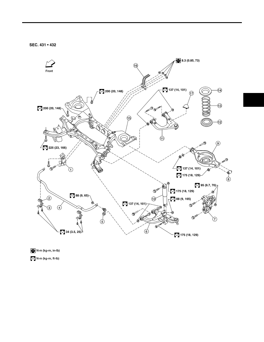
Components
EES0023B
On-Vehicle Inspection
EES0023C
●
Check all of the component mountings for any excessive looseness, or backlash. Repair or replace the
components as necessary.
1.
Seat belt latch anchor
2.
Stabilizer bar bushing
3.
Stabilizer bar clamp
4.
Stabilizer bar
5.
Connecting rod
6.
Front lower link
7.
Knuckle
8.
Bushing
9.
Rear lower link
10. Shock absorber
11.
Suspension arm
12. Lower rubber seat
13. Coil spring
14. Upper rubber seat
15. Rear suspension member
16. Spare tire bracket
17. Bound bumper
WEIA0130E