Nissan Pathfinder (2007 year). Manual - part 359
REAR FINAL DRIVE ASSEMBLY
RFD-21
C
E
F
G
H
I
J
K
L
M
A
B
RFD
2007 Pathfinder
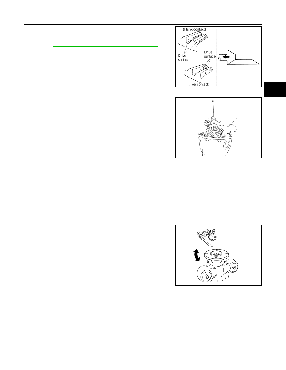
●
If the tooth contact is near the flank (flank contact), or near the
toe (toe contact), use a thinner drive pinion height adjusting
washers to move the drive pinion farther from the drive gear.
Refer to
RFD-39, "Drive Pinion Height Adjusting Washer"
.
Backlash
1.
Fit a dial indicator to the drive gear face to measure the back-
lash.
●
If the backlash is outside of the specification, change the thick-
ness of the side bearing adjusting washers.
CAUTION:
Do not change the total thickness of side bearing adjusting washers as it will change the side bearing
preload torque.
Companion Flange Runout
1.
Rotate companion flange and check for runout on the outer face
of the companion flange using suitable tool.
2.
If the runout is outside of the runout limit, follow the procedure
below to adjust.
a.
Rotate the companion flange on the drive pinion by 90
°
, 180
°
and 270
°
while checking for the position where the runout is
minimum.
b.
If the runout is still outside of the runout limit after the companion
flange has been rotated on the drive pinion, possible cause
could be an assembly malfunction of drive pinion and drive pin-
ion bearing or a malfunctioning drive pinion bearing.
c.
If the runout is still outside of the runout limit after repair of the assembly of drive pinion and drive pinion
bearing or drive pinion bearing, replace the companion flange.
DISASSEMBLY
Side Flange
1.
Drain the differential gear oil if necessary.
2.
Remove the side flange using Tools.
PDIA0441E
Backlash:
0.10 - 0.15 mm (0.0039 - 0.0059 in)
If the backlash is greater than specification:
Make side bearing adjusting washer thicker on drive
gear back side, and side bearing adjusting washer
thinner on drive gear tooth side by the same amount.
Refer to
RFD-39, "Side Bearing Adjusting Washer"
.
If the backlash is less than specification:
Make side bearing adjusting washer thinner on drive
gear back side, and side bearing adjusting washer
thicker on drive gear tooth side by the same amount.
Refer to
RFD-39, "Side Bearing Adjusting Washer"
.
SPD513
Runout limit
: 0.08 mm (0.0031 in) or less
WDIA0231E
Tool numbers
A: KV40104100 (
—
)
B: ST36230000 (J-25840-A)