Nissan Pathfinder (2007 year). Manual - part 300
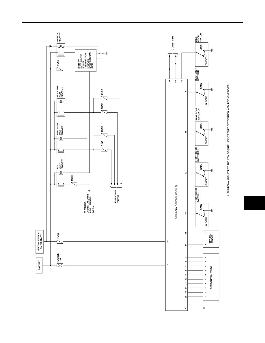
AUTO LIGHT SYSTEM
LT-41
C
D
E
F
G
H
I
J
L
M
A
B
LT
2007 Pathfinder
Schematic
EKS00FV3
WKWA5438E
|
|
|
AUTO LIGHT SYSTEM LT-41 C D E F G H I J L M A B LT 2007 Pathfinder Schematic EKS00FV3 WKWA5438E |