Nissan Pathfinder (2007 year). Manual - part 299
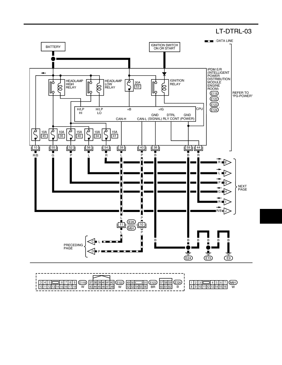
HEADLAMP (FOR CANADA) - DAYTIME LIGHT SYSTEM -
LT-33
C
D
E
F
G
H
I
J
L
M
A
B
LT
2007 Pathfinder
WKWA4225E
|
|
|
HEADLAMP (FOR CANADA) - DAYTIME LIGHT SYSTEM - LT-33 C D E F G H I J L M A B LT 2007 Pathfinder WKWA4225E |