Nissan Pathfinder (2007 year). Manual - part 288
TROUBLE DIAGNOSES WORK FLOW
LAN-35
[CAN FUNDAMENTAL]
C
D
E
F
G
H
I
J
L
M
A
B
LAN
2007 Pathfinder
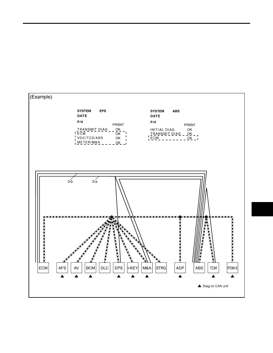
3.
CAN DIAG SUPPORT MNTR (without PAST): Check the CAN DIAG SUPPORT MNTR (without PAST) of
units indicating “U1000” or “U1001” on SELF-DIAG RESULTS. Draw a line on the diagnosis sheet to indi-
cate the possible error circuit.
NOTE:
●
While an error occurred in the past according to SELF-DIAG RESULTS, it is unclear which signal is not
received. Assume that errors were detected from all reception items.
●
Draw a single line among the unit and all reception items. (Work flow differs from CAN DIAG SUPPORT
MNTR (with PAST).)
a.
Reception item of “EPS”: Assume that the unit could not receive the signals from ECM, ABS, and M&A.
Draw a line among EPS, ECM, ABS, and M&A (line 3-a in the figure).
b.
Reception item of “ABS”: Assume that the unit could not receive the signal from ECM. Draw a line
between ABS and ECM (line 3-b in the figure).
SKIB8733E