Nissan Pathfinder (2007 year). Manual - part 287
TROUBLE DIAGNOSES WORK FLOW
LAN-27
[CAN FUNDAMENTAL]
C
D
E
F
G
H
I
J
L
M
A
B
LAN
2007 Pathfinder
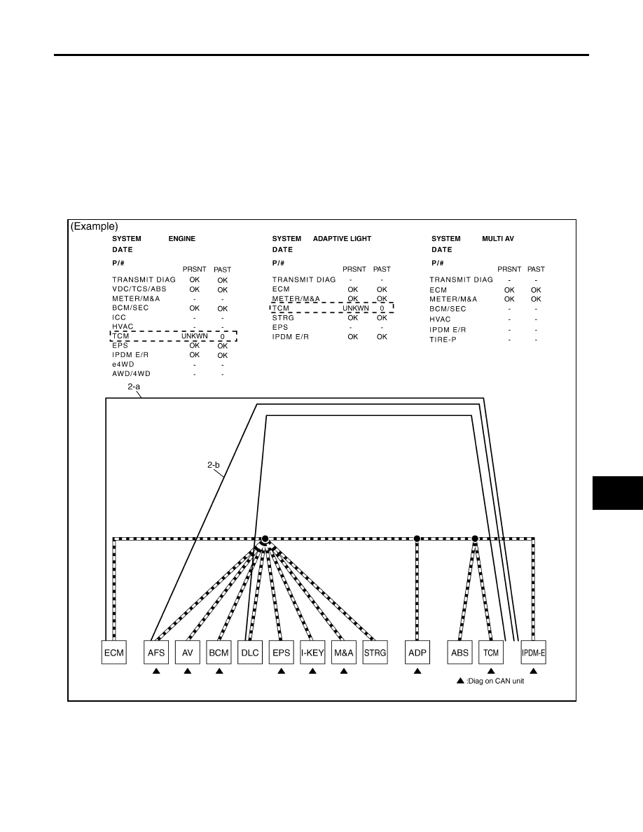
2.
CAN DIAG SUPPORT MNTR: Check each item on “CAN DIAG SUPPORT MNTR”. Draw a line on the
diagnosis sheet to indicate the error circuit.
a.
Reception item of “ENGINE”: On “TCM”, “UNKWN” is indicated. This means ECM cannot receive the sig-
nal from TCM. Draw a line to indicate an error between ECM and TCM (line 2-a in the figure).
NOTE:
If “UNKWN” is indicated on “TRANSMIT DIAG”, then the control unit cannot transmit CAN communication
signal to each unit. Draw a line between the control unit and the splice.
b.
Reception item of “ADAPTIVE LIGHT”: On “TCM”, “UNKWN” is indicated. This means AFS cannot
receive the signal from TCM. Draw a line to indicate an error between AFS and TCM (line 2-b in the fig-
ure).
c.
Reception item of “MULTI AV”: “UNKWN” is not indicated. This indicates normal communication between
AV and its receiving units. Do not draw any line.
SKIB8725E