Nissan Pathfinder (2007 year). Manual - part 284


  Index      Manuals     Nissan Pathfinder (2007 year) - Service and Repair Manual


Search            copyright infringement  


Content      ..     282      283      284      285     ..


Nissan Pathfinder (2007 year). Manual - part 284


PRECAUTIONS

LAN-3

[CAN FUNDAMENTAL]

C

D

E

F

G

H

I

J

L

M

A

B

LAN

2007 Pathfinder

PRECAUTIONS

PFP:00001

Precautions When Using CONSULT-II

UKS006H2

Use CONSULT-II CONVERTER when connecting CONSULT-II to data link connector.

CAUTION:

CAN communication does not function properly if CONSULT-II is used without connecting CONSULT-II
CONVERTER.

Precautions for Trouble Diagnosis

UKS006H3

CAUTION:

Never apply 7.0 V or more to the measurement terminal.

Use a tester with open terminal voltage of 7.0 V or less.

Turn the ignition switch OFF and disconnect the battery cable from the negative terminal when
checking the harness. 

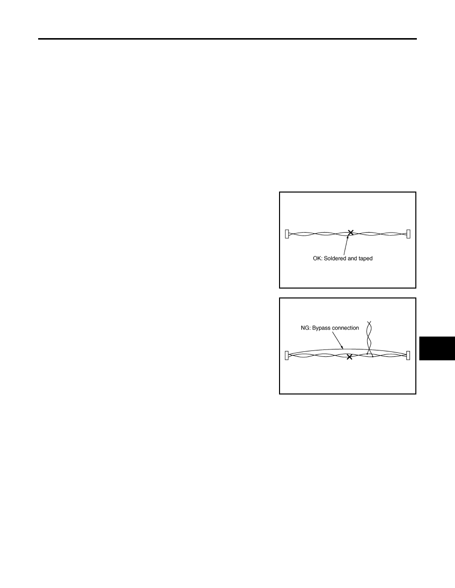
Precautions for Harness Repair

UKS006H4

Solder the repaired area and wrap tape around the soldered
area.

NOTE:
A fray of twisted lines must be within 110 mm (4.33 in).

Bypass connection is never allowed at the repaired area.

NOTE:
Bypass connection may cause CAN communication error. The
spliced wire becomes separated and the characteristics of
twisted line are lost. 

Replace the applicable harness as an assembly if error is detected on the shield lines of CAN communi-
cation line.

SKIB8766E

SKIB8767E

LAN-4

[CAN FUNDAMENTAL]

SYSTEM DESCRIPTION

2007 Pathfinder

SYSTEM DESCRIPTION

PFP:00000

CAN Communication System

UKS006H5

CAN communication is a multiplex communication system. This enables the system to transmit and
receive large quantities of data at high speed by connecting control units with two communication lines
(CAN-H and CAN-L).

Control units on the CAN network transmit signals using the CAN communication control circuit. They
receive only necessary signals from other control units to operate various functions.

CAN communication lines adopt twisted-pair line style (two lines twisted) for noise immunity.

SYSTEM DIAGRAM

Each control unit passes an electric current to the termination circuits when transmitting CAN communication
signal. The termination circuits produce an electrical potential difference between CAN-H and CAN-L. CAN
communication system transmits and receives CAN communication signals by the potential difference.

SKIB8887E

Component

Description

Main line

CAN communication line between splices

Branch line

CAN communication line between splice and a control unit

Splice

A point connecting a branch line with a main line

Termination circuit

Refer to 

LAN-5, "CAN COMMUNICATION CONTROL CIRCUIT"

 .

SYSTEM DESCRIPTION

LAN-5

[CAN FUNDAMENTAL]

C

D

E

F

G

H

I

J

L

M

A

B

LAN

2007 Pathfinder

CAN COMMUNICATION CONTROL CIRCUIT

*: These are the only control units wired with both ends of CAN communication system.

SKIB8713E

Component

System description

CAN controller

It controls CAN communication signal transmission and reception, error detection, etc.

Transceiver IC

It converts digital signal into CAN communication signal, and CAN communication signal into digi-
tal signal.

Noise filter

It eliminates noise of CAN communication signal.

Termination circuit

*

(Resistance of approx. 120 

)

It produces potential difference.

LAN-6

[CAN FUNDAMENTAL]

SYSTEM DESCRIPTION

2007 Pathfinder

Diag on CAN

UKS006H6

DESCRIPTION

“Diag on CAN” is a diagnosis using CAN communication instead of previous DDL1 and DDL2 communication
line, between control unit and diagnosis unit.

SYSTEM DIAGRAM

SKIB8714E

Name

Harness

Description

DDL1

Tx
Rx

It is used for trouble diagnosis. (CAN-H and CAN-L are used for controlling)

DDL2

K-LINE

It is used for trouble diagnosis. (CAN-H and CAN-L are used for controlling)

Diag on CAN

CAN-H
CAN-L

It is used for trouble diagnosis and control.

TROUBLE DIAGNOSIS

LAN-7

[CAN FUNDAMENTAL]

C

D

E

F

G

H

I

J

L

M

A

B

LAN

2007 Pathfinder

TROUBLE DIAGNOSIS

PFP:00004

Condition of Error Detection

UKS006H7

“U1000” or “U1001” is indicated on SELF-DIAG RESULTS on CONSULT-II if CAN communication signal is not
transmitted or received between units for 2 seconds or more.

CAN COMMUNICATION SYSTEM ERROR

CAN communication line open (CAN-H, CAN-L, or both)

CAN communication line short (ground, between CAN communication lines, other harnesses)

Error of CAN communication control circuit of the unit connected to CAN communication line

WHEN INDICATED “U1000” OR “U1001” IS INDICATED EVEN THOUGH CAN COMMUNICA-
TION SYSTEM IS NORMAL

CONSULT-II CONVERTER not connected: Error may be detected by the self-diagnosis when not using
CONSULT-II CONVERTER (Depending on the control unit which carries out CAN communication).

Removal/installation of parts: Error may be detected when removing and installing CAN communication
unit and related parts while turning the ignition switch ON. (A DTC except for CAN communication may be
detected.)

Fuse blown out (removed): CAN communication of the unit may cease.

Voltage drop: Error may be detected if voltage drops due to discharged battery when turning the ignition
switch ON (Depending on the control unit which carries out CAN communication).

Error may be detected if the power supply circuit of the control unit, which carries out CAN communica-
tion, malfunctions (Depending on the control unit which carries out CAN communication).

Error may be detected if reprogramming is not completed normally.

NOTE:
CAN communication system is normal if “U1000” or “U1001” is indicated on SELF-DIAG RESULTS of CON-
SULT-II under the above conditions. Erase the memory of the self-diagnosis of each unit.

LAN-8

[CAN FUNDAMENTAL]

TROUBLE DIAGNOSIS

2007 Pathfinder

Symptom When Error Occurs in CAN Communication System

UKS006H8

In CAN communication system, multiple units mutually transmit and receive signals. Each unit cannot transmit
and receive signals if any error occurs on CAN communication line. Under this condition, multiple control units
related to the root cause malfunction or go into fail-safe mode.

ERROR EXAMPLE

NOTE:

Each vehicle differs in symptom of each unit under fail-safe mode and CAN communication line wiring.

Refer to 

LAN-41, "Abbreviation List"

  for the unit abbreviation.

Example: TCM branch line open circuit

SKIB8738E

Unit name

Symptom

ECM

Engine torque limiting is affected, and shift harshness increases.

BCM

Reverse warning chime does not sound.

EPS control unit

Normal operation.

Combination meter

Shift position indicator and OD OFF indicator turn OFF.

Warning lamps turn ON.

ABS actuator and electric unit (control unit)

Normal operation.

TCM

No impact on operation.

IPDM E/R

Normal operation.

TROUBLE DIAGNOSIS

LAN-9

[CAN FUNDAMENTAL]

C

D

E

F

G

H

I

J

L

M

A

B

LAN

2007 Pathfinder

Example: Data link connector branch line open circuit

NOTE:

When data link connector branch line is open, transmission and reception of CAN communication signals
is not affected. Therefore, no symptoms occur. However, be sure to repair malfunctioning circuit.

When data link connector branch line is open, the screen-display of the CONSULT-II “SELECT SYSTEM”
screen may be the same as when the CAN communication line has short-circuit. However, symptoms dif-
fer depending on the case. See below chart for the differences.

SKIB8739E

Unit name

Symptom

ECM

Normal operation.

BCM

EPS control unit

Combination meter

ABS actuator and electric unit (control unit)

TCM

IPDM E/R

SELECT SYSTEM

(CONSULT-II)

Difference of symptom

Data link connector branch line open cir-
cuit

All Diag on CAN units are not 
indicated.

Normal operation.

CAN-H, CAN-L harness short-circuit

Most the units which are connected to the CAN com-
munication system enter fail-safe mode or are deac-
tivated.

LAN-10

[CAN FUNDAMENTAL]

TROUBLE DIAGNOSIS

2007 Pathfinder

Example: Main Line Between Data Link Connector and ABS Actuator and Electric Unit (Con-
trol Unit) Open Circuit

SKIB8740E

Unit name

Symptom

ECM

Engine torque limiting is affected, and shift harshness increases.

BCM

Reverse warning chime does not sound.

The front wiper moves under continuous operation mode even though the front 
wiper switch being in the intermittent position.

EPS control unit

The steering effort increases.

Combination meter

The shift position indicator and OD OFF indicator turn OFF.

The speedometer is inoperative.

The odo/trip meter stops.

ABS actuator and electric unit (control unit)

Normal operation.

TCM

No impact on operation.

IPDM E/R

When the ignition switch is ON,

The headlamps (Lo) turn ON.

The cooling fan continues to rotate.


Content      ..     282      283      284      285     ..