Nissan Pathfinder (2007 year). Manual - part 270
WINDSHIELD GLASS
GW-13
C
D
E
F
G
H
J
K
L
M
A
B
GW
2007 Pathfinder
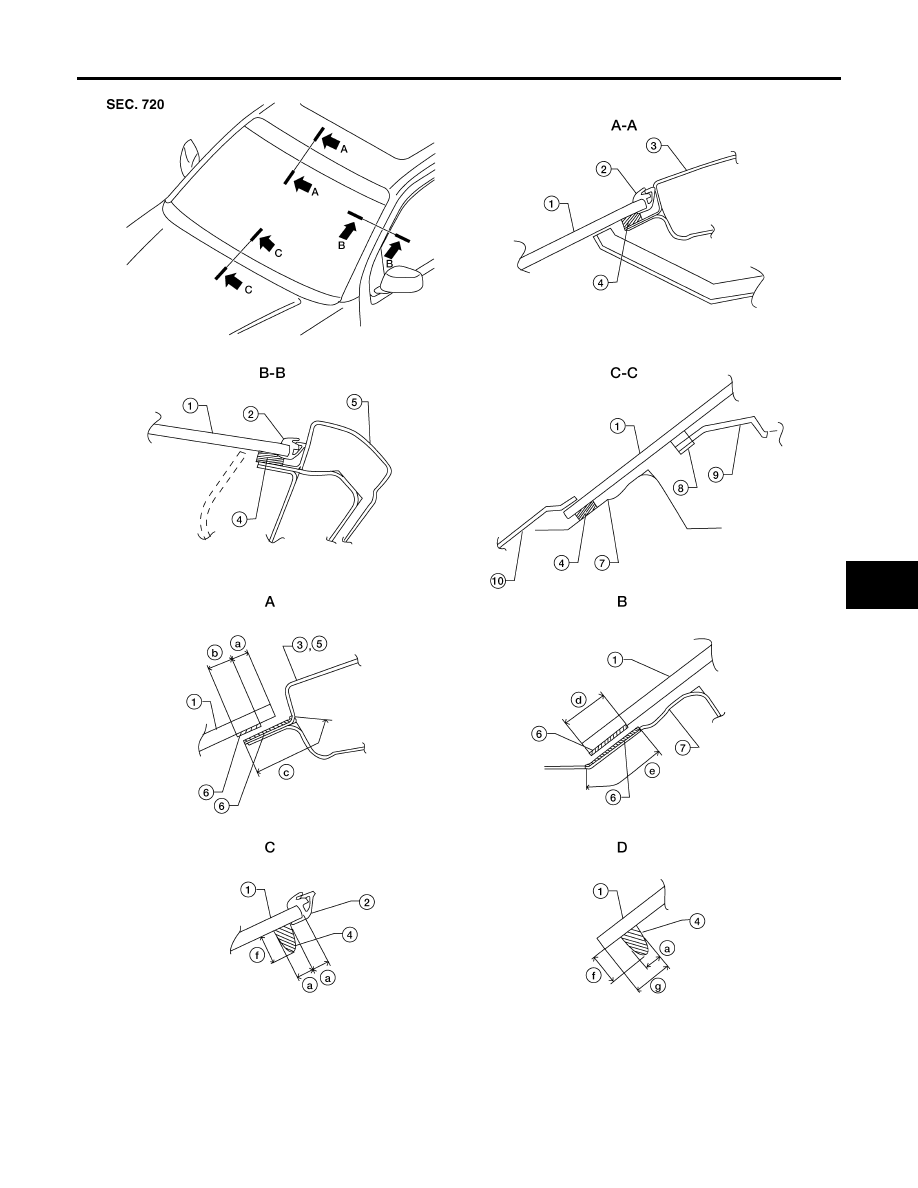
1.
Windshield glass
2.
Molding
3.
Roof
4.
Urethane
5.
A-pillar
6.
Primer
7.
Cowl top panel
8.
Insulator
9.
Instrument panel
WIIA1032E