Nissan Pathfinder (2007 year). Manual - part 230
LUGGAGE FLOOR TRIM
EI-33
C
D
E
F
G
H
J
K
L
M
A
B
EI
2007 Pathfinder
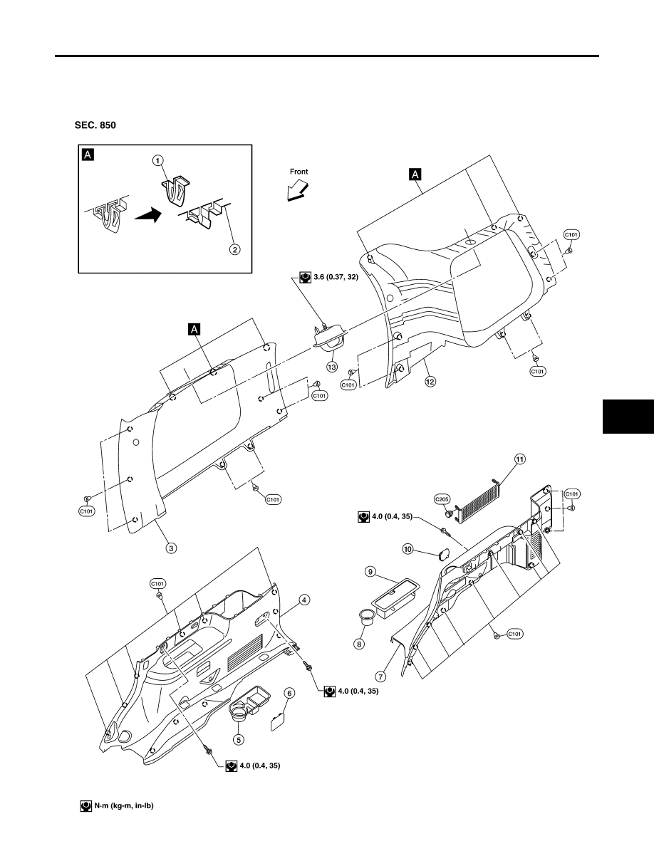
LUGGAGE FLOOR TRIM
PFP:84999
Components
EIS007U8
Luggage Trim - Side
LIIA1783E
|
|
|
LUGGAGE FLOOR TRIM EI-33 C D E F G H J K L M A B EI 2007 Pathfinder LUGGAGE FLOOR TRIM PFP:84999 Components EIS007U8 Luggage Trim - Side LIIA1783E |