Nissan Pathfinder (2007 year). Manual - part 182
DTC P0172, P0175 FUEL INJECTION SYSTEM FUNCTION
EC-323
C
D
E
F
G
H
I
J
K
L
M
A
EC
2007 Pathfinder
5.
DETECT MALFUNCTIONING PART
Check the following.
●
Fuel pump and circuit (Refer to,
.)
●
Fuel pressure regulator (Refer to
>> Repair or replace.
6.
CHECK MASS AIR FLOW SENSOR
With CONSULT-II
1.
Install all removed parts.
2.
Check “MASS AIR FLOW” in “DATA MONITOR” mode with CONSULT-II.
OK or NG
OK
>> GO TO 8.
NG
>> Check connectors for rusted terminals or loose connections in the mass air flow sensor circuit or
ground. Refer to
.
7.
CHECK MASS AIR FLOW SENSOR
With GST
1.
Install all removed parts.
2.
Check mass air flow sensor signal in Service $01 with GST.
OK or NG
OK (P0172)>>GO TO 9.
OK (P0175)>>GO TO 11.
NG
>> Check connectors for rusted terminals or loose connections in the mass air flow sensor circuit or
ground. Refer to
.
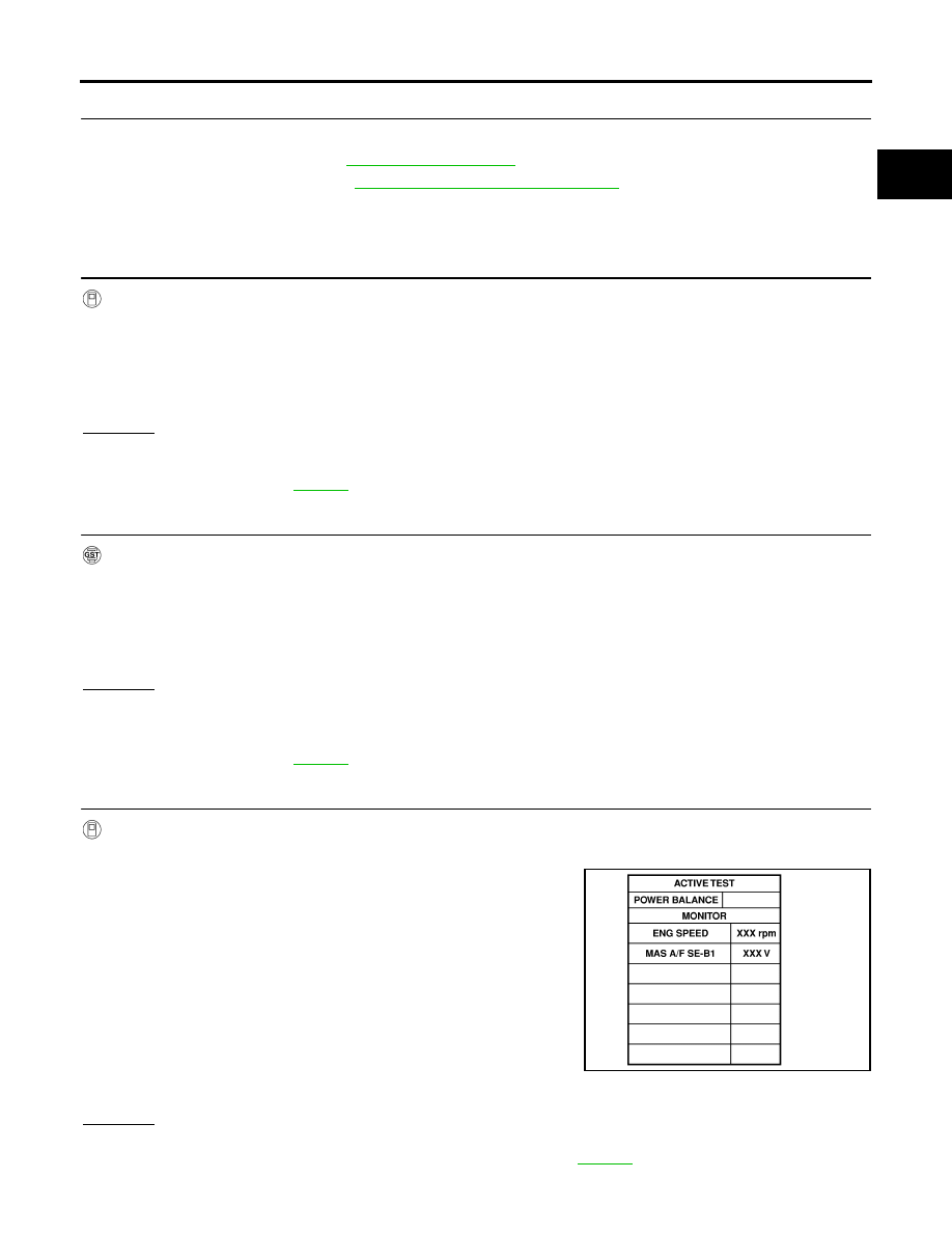
8.
CHECK FUNCTION OF FUEL INJECTOR
With CONSULT-II
1.
Start engine.
2.
Perform “POWER BALANCE” in “ACTIVE TEST” mode with
CONSULT-II.
3.
Make sure that each circuit produces a momentary engine
speed drop.
OK or NG
OK
>> GO TO 12.
NG
>> Perform trouble diagnosis for FUEL INJECTOR, refer to
2.0 - 6.0 g·m/sec:
at idling
7.0 - 20.0 g·m/sec:
at 2,500 rpm
2.0 - 6.0 g·m/sec:
at idling
7.0 - 20.0 g·m/sec:
at 2,500 rpm
PBIB0133E