Nissan Pathfinder (2007 year). Manual - part 180
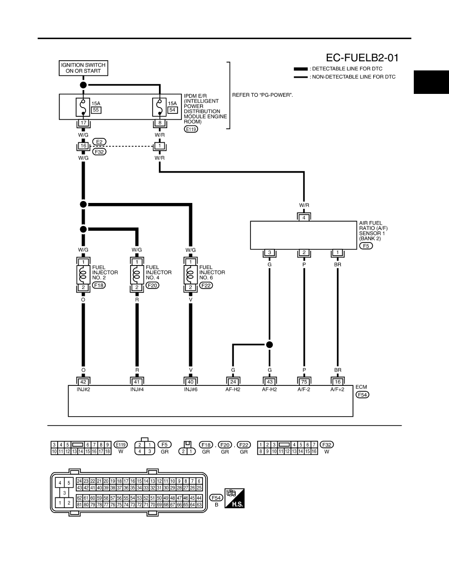
DTC P0171, P0174 FUEL INJECTION SYSTEM FUNCTION
EC-307
C
D
E
F
G
H
I
J
K
L
M
A
EC
2007 Pathfinder
BANK 2
BBWA2820E
|
|
|
DTC P0171, P0174 FUEL INJECTION SYSTEM FUNCTION EC-307 C D E F G H I J K L M A EC 2007 Pathfinder BANK 2 BBWA2820E |