Nissan Pathfinder (2007 year). Manual - part 173


  Index      Manuals     Nissan Pathfinder (2007 year) - Service and Repair Manual


Search            copyright infringement  


Content      ..     171      172      173      174     ..


Nissan Pathfinder (2007 year). Manual - part 173


DTC P0132, P0152 A/F SENSOR 1

EC-251

C

D

E

F

G

H

I

J

K

L

M

A

EC

2007 Pathfinder

2. 

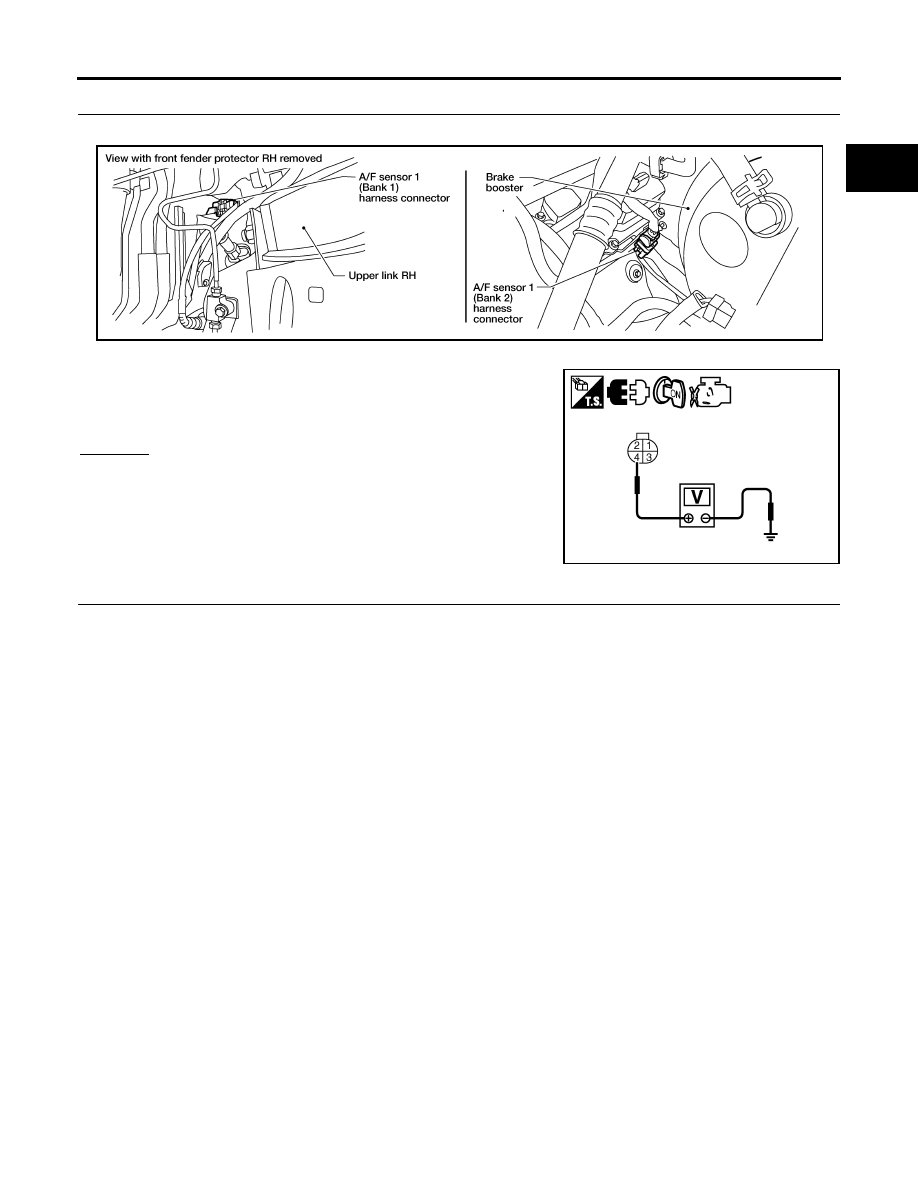
CHECK AIR FUEL RATIO (A/F) SENSOR 1 POWER SUPPLY CIRCUIT

1.

Disconnect A/F sensor 1 harness connector.

2.

Turn ignition switch ON.

3.

Check voltage between A/F sensor 1 terminal 4 and ground with
CONSULT-II or tester.

OK or NG

OK

>> GO TO 4.

NG

>> GO TO 3.

3. 

DETECT MALFUNCTIONING PART

Check the following.

Harness connectors E2, F32

IPDM E/R connector E119

15A fuse

Harness for open or short between A/F sensor 1 and fuse

>> Repair or replace harness or connectors.

Voltage: Battery voltage

BBIA0544E

PBIB3308E

EC-252

DTC P0132, P0152 A/F SENSOR 1

2007 Pathfinder

4. 

CHECK A/F SENSOR 1 INPUT SIGNAL CIRCUIT FOR OPEN AND SHORT

1.

Turn ignition switch OFF.

2.

Disconnect ECM harness connector.

3.

Check harness continuity between A/F sensor 1 terminal and ECM terminal as follows.
Refer to Wiring Diagram.

4.

Check harness continuity between the following terminals and ground.
Refer to Wiring Diagram.

5.

Also check harness for short to power.

OK or NG

OK

>> GO TO 5.

NG

>> Repair open circuit or short to ground or short to power in harness or connectors.

5. 

CHECK INTERMITTENT INCIDENT

Perfor

EC-145, "TROUBLE DIAGNOSIS FOR INTERMITTENT INCIDENT"

 .

OK or NG

OK

>> GO TO 6.

NG

>> Repair or replace.

6. 

REPLACE A/F SENSOR 1

Replace malfunctioning A/F sensor 1.

CAUTION:

Discard any A/F sensor which has been dropped from a height of more than 0.5 m (19.7 in) onto a
hard surface such as a concrete floor; use a new one.

Before installing new A/F sensor, clean exhaust system threads using Heated Oxygen Sensor
Thread Cleaner tool J-43897-18 or J-43897-12 and approved anti-seize lubricant.

>> INSPECTION END

Removal and Installation

UBS00KEF

AIR FUEL RATIO (A/F) SENSOR 1

Refer to 

EM-22, "EXHAUST MANIFOLD AND THREE WAY CATALYST"

 .

A/F sensor 1 terminal

ECM terminal

Bank1

1

35

2

56

Bank 2

1

16

2

75

Continuity should exist.

Bank 1

Bank 2

A/F sensor 1 terminal

ECM terminal

A/F sensor 1 terminal

ECM terminal

1

35

1

16

2

56

2

75

Continuity should not exist.

DTC P0133, P0153 A/F SENSOR 1

EC-253

C

D

E

F

G

H

I

J

K

L

M

A

EC

2007 Pathfinder

DTC P0133, P0153 A/F SENSOR 1

PFP:22693

Component Description

UBS00KF2

The air fuel ratio (A/F) sensor 1 is a planar one-cell limit current sen-
sor. The sensor element of the A/F sensor 1 is composed an elec-
trode layer, which transports ions. It has a heater in the element.
The sensor is capable of precise measurement   = 1, but also in the
lean and rich range. Together with its control electronics, the sensor
outputs a clear, continuous signal throughout a wide   range.
The exhaust gas components diffuse through the diffusion layer at
the sensor cell. An electrode layer is applied voltage, and this current
relative oxygen density in lean. Also this current relative hydrocar-
bon density in rich.
Therefore, the A/F sensor 1 is able to indicate air fuel ratio by this
electrode layer of current. In addition, a heater is integrated in the
sensor to ensure the required operating temperature of about 800

°

C

(1,472

°

F).

CONSULT-II Reference Value in Data Monitor Mode

UBS00KF3

Specification data are reference values.

On Board Diagnosis Logic

UBS00KF4

To judge the malfunction of A/F sensor 1, this diagnosis measures response time of the A/F signal computed
by ECM from the A/F sensor 1 signal. The time is compensated by engine operating (speed and load), fuel
feedback control constant, and the A/F sensor 1 temperature index. Judgment is based on whether the com-
pensated time (the A/F signal cycling time index) is inordinately long or not.

PBIB3353E

PBIB3354E

MONITOR ITEM

CONDITION

SPECIFICATION

A/F SEN1 (B1)
A/F SEN1 (B2)

Engine: After warming up

Maintaining engine speed at 
2,000 rpm

 Fluctuates around 2.2V

DTC No.

Trouble diagnosis name

DTC detecting condition

Possible Cause

P0133
0133
(Bank 1)

Air fuel ratio (A/F) sensor 1 
circuit slow response

The response of the A/F signal computed by 
ECM from A/F sensor 1 signal takes more than 
the specified time.

Harness or connectors
(The A/F sensor 1 circuit is open or 
shorted.)

A/F sensor 1

A/F sensor 1 heater

Fuel pressure

Fuel injector

Intake air leaks

Exhaust gas leaks

PCV

Mass air flow sensor

P0153
0153
(Bank 2)

EC-254

DTC P0133, P0153 A/F SENSOR 1

2007 Pathfinder

DTC Confirmation Procedure

UBS00KF5

NOTE:
If DTC Confirmation Procedure has been previously conducted, always turn ignition switch OFF and wait at
least 10 seconds before conducting the next test.
TESTING CONDITION:
Before performing the following procedure, confirm that battery voltage is more than 11V at idle.

 WITH CONSULT-II

1.

Start engine and warm it up to normal operating temperature.

2.

Turn ignition switch OFF and wait at least 10 seconds.

3.

Start engine and keep the engine speed between 3,500 and 4,000 rpm for at least 1minute under no load.

4.

Let engine idle for 1 minute.

5.

Select “A/F SEN1(B1) P1278/P1279” (for DTC P0133) or “A/F SEN1(B1) P1288/P1289” (for DTC P0153)
of “A/F SEN1” in “DTC WORK SUPPORT” mode with CONSULT-II.

6.

Touch “START”.
If “COMPLETED” appears on CONSULT-II screen, go to step
10.
If “COMPLETED” does not appear on CONSULT-II screen, go to
the following step.

7.

After perform the following procedure, “TESTING” will be dis-
played on the CONSULT-II screen.

a.

Increase the engine speed up to 4,000 to 5,000 rpm and keep it
for 10 seconds.

b.

Fully release accelerator pedal and then let engine idle for about
10 seconds.
If “TESTING” is not displayed after 10 seconds, refer to 

EC-

135, "TROUBLE DIAGNOSIS - SPECIFICATION VALUE"

 .

8.

Wait for about 20 seconds at idle at under the condition that
“TESTING” is displayed on the CONSULT-II screen.

9.

Make sure that “TESTING” changes to “COMPLETED”.
If “TESTING” changed to “OUT OF CONDITION”, refer to

EC-135, "TROUBLE DIAGNOSIS - SPECIFICATION VALUE"

 . 

10. Make sure that “OK” is displayed after touching “SELF-DIAG

RESULT”.
If “NG” is displayed, go to 

EC-259, "Diagnostic Procedure"

 .

 WITH GST

1.

Start engine and warm it up to normal operating temperature.

2.

Select Service $01 with GST.

3.

Calculate the total value of “Short term fuel trim” and “Long term fuel trim” indications.
Make sure that the total percentage should be within 

±

15%.

If OK, go to the following step.
If NG, check the following.

PBIB0756E

PBIB1925E

PBIB0758E

DTC P0133, P0153 A/F SENSOR 1

EC-255

C

D

E

F

G

H

I

J

K

L

M

A

EC

2007 Pathfinder

Intake air leaks

Exhaust gas leaks

Incorrect fuel pressure

Lack of fuel

Fuel injector

Incorrect PCV hose connection

PCV valve

Mass air flow sensor

4.

Turn ignition switch OFF and wait at least 10 seconds.

5.

Start engine and keep the engine speed between 3,500 and 4,000 rpm for at least 1minute under no load.

6.

Let engine idle for 1 minute.

7.

Increase the engine speed up to 4,000 to 5,000 rpm and keep it for 10 seconds.

8.

Fully release accelerator pedal and then let engine idle for about 1 minute.

9.

Select Service $03 with GST and make sure that no DTC is displayed.
If the DTC is displayed, go to 

EC-259, "Diagnostic Procedure"

 .

EC-256

DTC P0133, P0153 A/F SENSOR 1

2007 Pathfinder

Wiring Diagram

UBS00KF6

BANK 1

BBWA2811E

DTC P0133, P0153 A/F SENSOR 1

EC-257

C

D

E

F

G

H

I

J

K

L

M

A

EC

2007 Pathfinder

Specification data are reference values and are measured between each terminal and ground.
Pulse signal is measured by CONSULT-II.

CAUTION:

Do not use ECM ground terminals when measuring input/output voltage. Doing so may result in dam-
age to the ECM's transistor. Use a ground other than ECM terminals, such as the ground.

: Average voltage for pulse signal (Actual pulse signal can be confirmed by oscilloscope.)

TER-

MINAL 

NO.

WIRE 

COLOR

ITEM

CONDITION

DATA (DC Voltage)

2

G

A/F sensor 1 heater (Bank 1)

[Engine is running]

Warm-up condition

Idle speed
(More than 140 seconds after starting 
engine)

Approximately 2.9 - 8.8V

35

O

A/F sensor 1 (Bank 1)

[Engine is running]

Warm-up condition

Engine speed: 2,000 rpm

Approximately 1.8V
Output voltage varies with air 
fuel ratio.

56

LG

A/F sensor 1 (Bank 1)

[Ignition switch: ON]

Approximately 2.2V

PBIA8148J

EC-258

DTC P0133, P0153 A/F SENSOR 1

2007 Pathfinder

BANK 2

BBWA2812E


Content      ..     171      172      173      174     ..