Nissan Pathfinder (2007 year). Manual - part 152
TROUBLE DIAGNOSIS
EC-83
C
D
E
F
G
H
I
J
K
L
M
A
EC
2007 Pathfinder
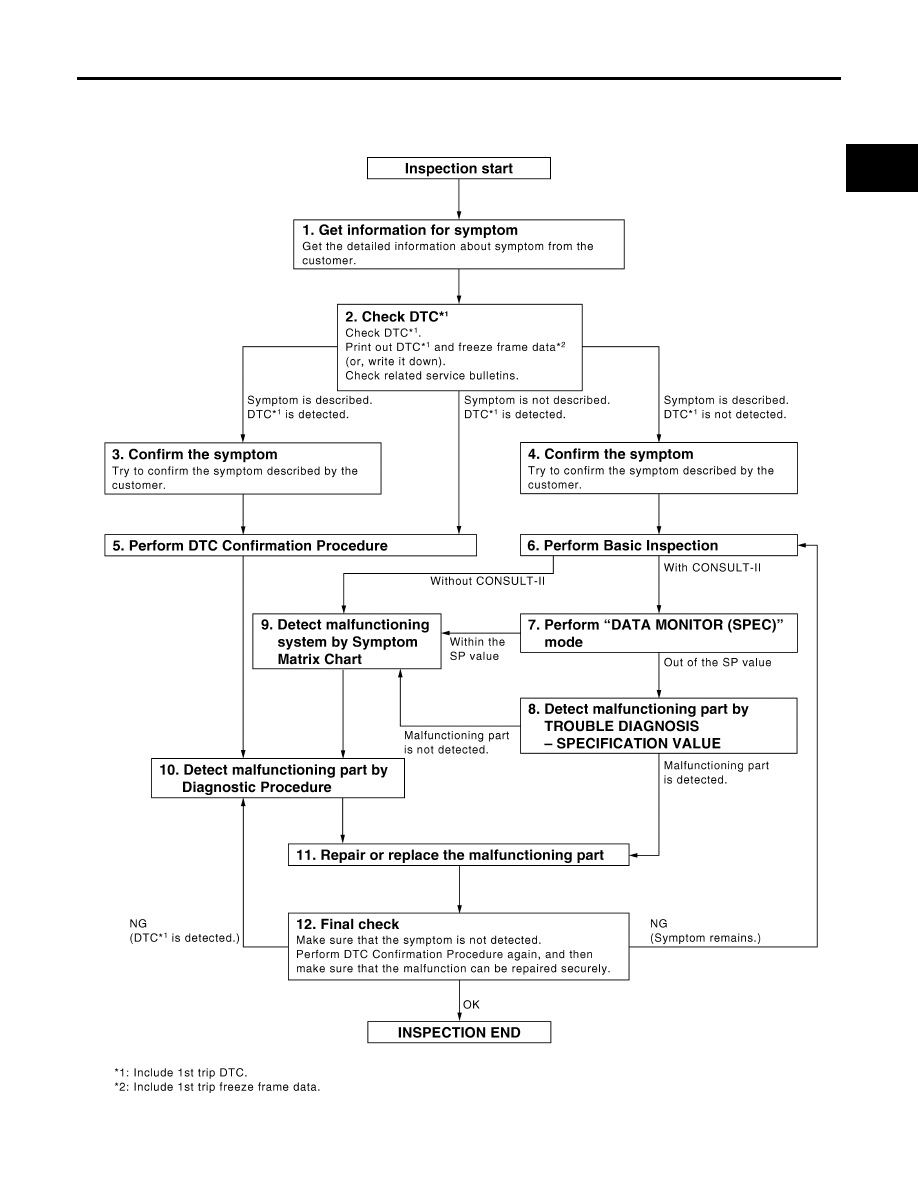
WORK FLOW
Overall Sequence
PBIB2267E
|
|
|
TROUBLE DIAGNOSIS EC-83 C D E F G H I J K L M A EC 2007 Pathfinder WORK FLOW PBIB2267E |