Nissan Pathfinder (2007 year). Manual - part 93


  Index      Manuals     Nissan Pathfinder (2007 year) - Service and Repair Manual


Search            copyright infringement  


Content      ..     91      92      93      94     ..


Nissan Pathfinder (2007 year). Manual - part 93


POWER DOOR LOCK SYSTEM

BL-37

C

D

E

F

G

H

J

K

L

M

A

B

BL

2007 Pathfinder

Front Door Lock Assembly LH (Key Cylinder Switch) Check

EIS007OU

1. 

CHECK DOOR KEY CYLINDER SWITCH LH

With CONSULT-II

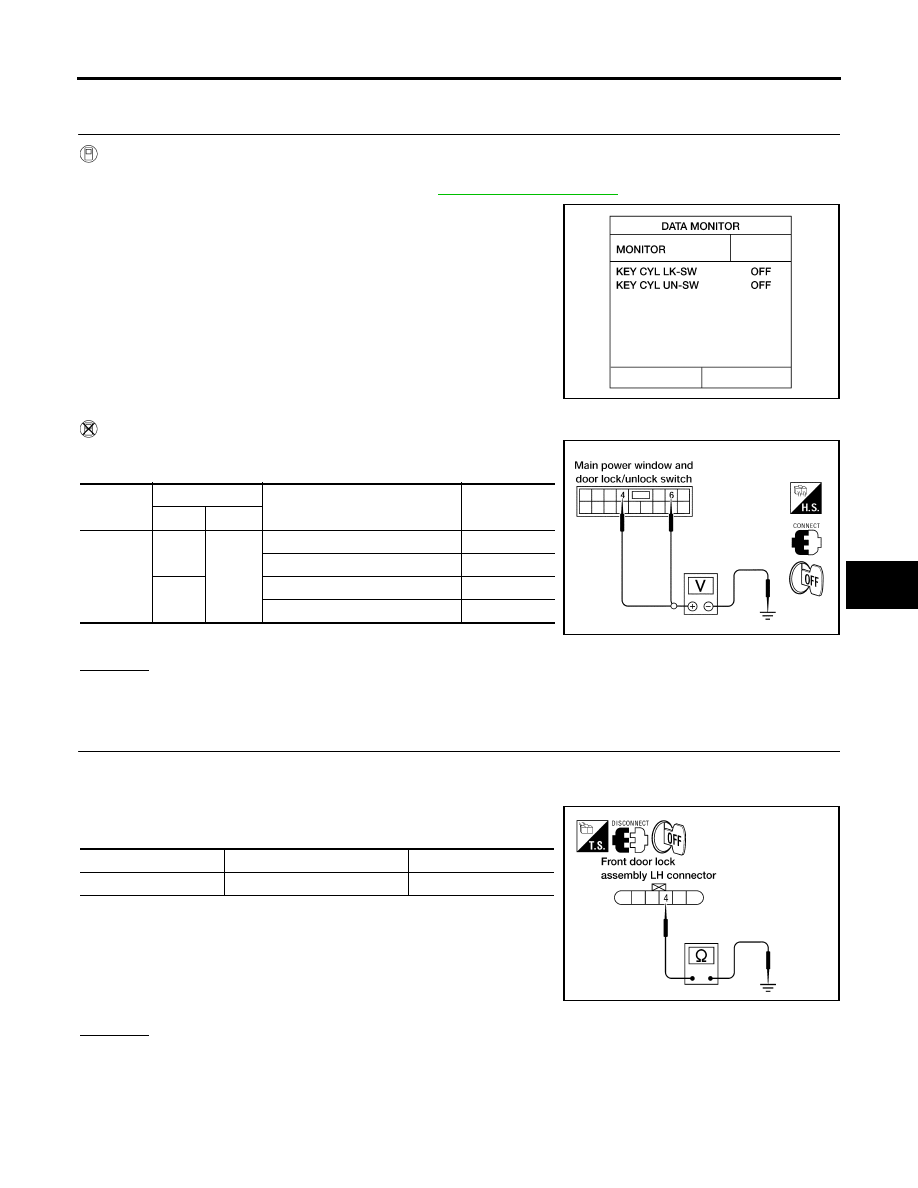
Check front door lock assembly LH (key cylinder switch) ("KEY CYL LK-SW") and ("KEY CYL UN-SW) in
DATA MONITOR mode with CONSULT–II. Refer to 

BL-25, "DATA MONITOR"

 .

When key inserted in left front key cylinder is turned to LOCK:

When key inserted in left front key cylinder is turned to
UNLOCK:

Without CONSULT-II

Check voltage between main power window and door lock/unlock
switch connector D7 terminals 4, 6 and ground.

OK or NG

OK

>> Key cylinder switch signal is OK.

NG

>> GO TO 2.

2. 

CHECK DOOR KEY CYLINDER SWITCH LH GROUND HARNESS

1.

Turn ignition switch OFF.

2.

Disconnect front door lock assembly LH (key cylinder switch).

3.

Check continuity between front door lock assembly LH (key cyl-
inder switch) connector D14 terminal 4 and body ground.

OK or NG

OK

>> GO TO 3.

NG

>> Repair or replace harness.

KEY CYL LK-SW

: ON

KEY CYL UN-SW

: ON

LIIA0188E

Connector

Terminals

Condition of left front key cylinder

Voltage (V)

(Approx.)

(+)

(–)

D7

4

Ground

Neutral/Unlock

5

Lock

0

6

Neutral/Lock

5

Unlock

0

LIIA0566E

Connector

Terminals

Continuity

D14

4 – Ground

Yes

WIIA0677E

BL-38

POWER DOOR LOCK SYSTEM

2007 Pathfinder

3. 

CHECK FRONT DOOR LOCK ASSEMBLY LH (KEY CYLINDER SWITCH)

Check continuity between front door lock assembly LH (key cylinder
switch) terminals 3, 4 and 5.

OK or NG

OK

>> GO TO 4.

NG

>> Replace front door lock assembly LH (key cylinder switch). Refer to 

BL-89, "Removal and Installa-

tion"

 .

4. 

CHECK DOOR KEY CYLINDER HARNESS

Check continuity between main power window and door lock/unlock
switch connector (A) D7 terminals 4, 6 and front door lock assembly
LH (key cylinder switch) connector (B) D14 terminals 3, 5 and body
ground. 

OK or NG

OK

>> Replace main power window and door lock/unlock switch.

NG

>> Repair or replace harness.

Terminals

Condition

Continuity

4 – 5

Key is turned to LOCK.

Yes

Key is in N position or turned to 

UNLOCK

No

3 – 4

Key is turned to UNLOCK.

Yes

Key is in N position or turned to LOCK

No

WIIA0458E

Connector

Terminals

Connector

Terminals

Continuity

A: Main 

power win-

dow and 

door lock/

unlock 

switch

4

B:  Front 

door lock 

assembly 

LH (key 
cylinder 

switch)

5

Yes

6

3

Yes

4, 6

Ground

No

WIIA1313E

REMOTE KEYLESS ENTRY SYSTEM

BL-39

C

D

E

F

G

H

J

K

L

M

A

B

BL

2007 Pathfinder

REMOTE KEYLESS ENTRY SYSTEM

PFP:28596

Component Parts and Harness Connector Location

EIS007OV

LIIA2412E

1.

IPDM E/R E118, E119, E120, E121, 
E122, E123, E124

2.

Horns E3, E162
(behind front combination lamp LH)

3.

Back door switch D502
Back door lock actuator D508

4.

Front door switch
LH B8
RH B108

5.

Rear door switch
LH B18
RH B116

6.

Remote keyless entry receiver M120
(view with instrument panel RH 
removed)

7.

Steering member

8.

BCM M18, M19, M20
(view with instrument lower panel LH 
removed)

9.

Key switch M27

BL-40

REMOTE KEYLESS ENTRY SYSTEM

2007 Pathfinder

System Description

EIS007OW

INPUTS

Power is supplied at all times

to BCM (body control module) terminal 70

through 50A fusible link (letter g , located in the fuse and fusible link box).

to BCM terminal 57

through 10A fuse [No. 18, located in the fuse block (J/B)].

When the key is inserted in the ignition cylinder (key switch), power is supplied

to BCM terminal 37

through key switch terminals 1 and 2

through 10A fuse (No. 25, located in the fuse and fusible link box).

When the ignition switch is ACC or ON, power is supplied

to BCM terminal 11

through 10A fuse [No. 4, located in the fuse block (J/B)].

When the ignition switch is ON or START, power is supplied

to BCM terminal 38

through 10A fuse [No. 1, located in the fuse block (J/B)].

When the front door switch LH is ON (door is OPEN), ground is supplied

to BCM terminal 47

through front door switch LH terminal 2

through front door switch LH case ground.

When the front door switch RH is ON (door is OPEN), ground is supplied

to BCM terminal 12

through front door switch RH terminal 2

through front door switch RH case ground.

When the rear door switch LH is ON (door is OPEN), ground is supplied

to BCM terminal 48

through rear door switch LH terminal 2

through rear door switch LH case ground.

When the rear door switch RH is ON (door is OPEN), ground is supplied

to BCM terminal 13

through rear door switch RH terminal 2

through rear door switch RH case ground.

When the back door switch is ON (door is OPEN), ground is supplied

to BCM terminal 43

through back door switch terminal 3,

through back door switch terminal 1,

through body grounds D406 and D504.

Keyfob signal is inputted to BCM from the remote keyless entry receiver.
The remote keyless entry system controls operation of the

power door lock

interior lamp and ignition keyhole illumination

panic alarm

hazard and horn reminder

auto door lock operation

OPERATED PROCEDURE

When the keyfob is operated, the signal from the keyfob is sent and the remote keyless entry receiver
receives the signal and sends it to the BCM. The BCM only locks/unlocks the doors if the ID number
matches. (Remote control entry functions)

REMOTE KEYLESS ENTRY SYSTEM

BL-41

C

D

E

F

G

H

J

K

L

M

A

B

BL

2007 Pathfinder

Using the keyfob, the transmitter sends radio waves to the remote keyless entry receiver, which then
sends the received waves to the BCM. Only if the ID number matches does the BCM lock/unlock the
doors. (Remote control door function)

Unless the key is inserted into the ignition key cylinder or one of the doors is opened within 1 minute after
the UNLOCK switch on the keyfob is pressed, all the doors are automatically locked. (Auto lock function)

When a door is locked or unlocked, the vehicle turn signal lamps flash and the horn sounds to verify oper-
ation. (Active check function)

When the key is in the ignition key cylinder (when the key switch is ON) and one of the doors is open, the
door lock function does not work even when the door lock is operated with the keyfob. 

Keyfob ID set up is available.

If a keyfob is lost, a new keyfob can be set up. A maximum of 5 IDs can be set up simultaneously.

Remote Control Entry Functions

Operation Description

When a button on the keyfob is operated, the signal is sent from the keyfob and received by the remote
keyless entry receiver.

The received signal is sent to the BCM and compared with the registered ID number.

If the ID number matches, the BCM sends the lock/unlock signal to each door lock actuator. 

When the door lock actuators receive this signal, each operates to lock/unlock its door.

BCM locks all doors with input of LOCK signal from keyfob.

When an UNLOCK signal is sent from keyfob once, driver's door will be unlocked.

Then, if an UNLOCK signal is sent from keyfob again within 5 seconds, all other doors will be unlocked.

Remote control entry operation conditions

Auto Lock Function

Operation Description

Unless the key is inserted into the ignition key cylinder, one of the doors is opened, or the keyfob is oper-
ated within 1 minute after a door lock is unlocked by keyfob operation, all the doors are automatically
locked.
The 1 minute timer count is executed by the BCM and after 1 minute, the BCM sends the lock signal to all
doors.

NOTE:
On vehicles with NAVI, this time can be adjusted via the display. Refer to Owner's Manual for instructions.

Lock operations are the same as for the remote control entry function.

Active Check Function

Operation Description
When a door is locked or unlocked by keyfob operation, the vehicle turn signals flash and the horn sounds to
verify operation.

When a button on the keyfob is operated, the signal is sent from the remote controller and received by the
keyless remote entry receiver.

The received signal is sent to the BCM and compared with the registered ID number.

If the ID number matches, the BCM uses communication to send the turn signal flashing and horn signal
to the IPDM E/R.

The IPDM E/R flashes the turn signal lamps and sounds the horn for each keyfob operation.

Keyfob operation

Operation condition

Door lock operation (locking)

With key removed (key switch: OFF)

Closing all doors (door switch: OFF)

Door lock operation (unlocking)

With key removed (key switch: OFF)

BL-42

REMOTE KEYLESS ENTRY SYSTEM

2007 Pathfinder

Operating function of hazard and horn reminder

Hazard and Horn Reminder

BCM output to IPDM E/R for horn reminder signal as DATA LINE (CAN-H line and CAN-L line).
The hazard and horn reminder has C mode (horn chirp mode) and S mode (non-horn chirp mode).
How to change hazard and horn reminder mode

 With CONSULT-II

Hazard and horn reminder can be changed using “WORK SUPPORT” mode in “MULTI ANSWER BACK SET".

 Without CONSULT-II

Refer to Owner's Manual for instructions.

Interior Lamp and Ignition Keyhole Illumination Operation

When the following input signals are both supplied:

all door switches are in the OFF position. (when all the doors are closed);

interior lamp switch is in DOOR position.

Remote keyless entry system turns on interior lamp and ignition keyhole illumination (for 30 seconds) with
input of UNLOCK signal from keyfob.
For detailed description, refer to 

LT-110, "ROOM LAMP TIMER OPERATION"

 .

Panic Alarm Operation

When key switch is OFF (when ignition key is not inserted in key cylinder), remote keyless entry system turns
on and off horn and headlamp intermittently with input of PANIC ALARM signal from keyfob.
The alarm automatically turns off after 25 seconds or when BCM receives any signal from keyfob.

CAN Communication System Description

EIS007OX

Refer to 

LAN-4, "SYSTEM DESCRIPTION"

 .

C mode

S mode

Keyfob operation

Lock

Unlock

Lock

Unlock

Hazard warning lamp 
flash

Twice

Once

Twice

Horn sound

Once

REMOTE KEYLESS ENTRY SYSTEM

BL-43

C

D

E

F

G

H

J

K

L

M

A

B

BL

2007 Pathfinder

Schematic

EIS007OY

WIWA1623E

BL-44

REMOTE KEYLESS ENTRY SYSTEM

2007 Pathfinder

Wiring Diagram — KEYLES —

EIS007OZ

WIWA1613E


Content      ..     91      92      93      94     ..