Nissan Pathfinder (2007 year). Manual - part 91
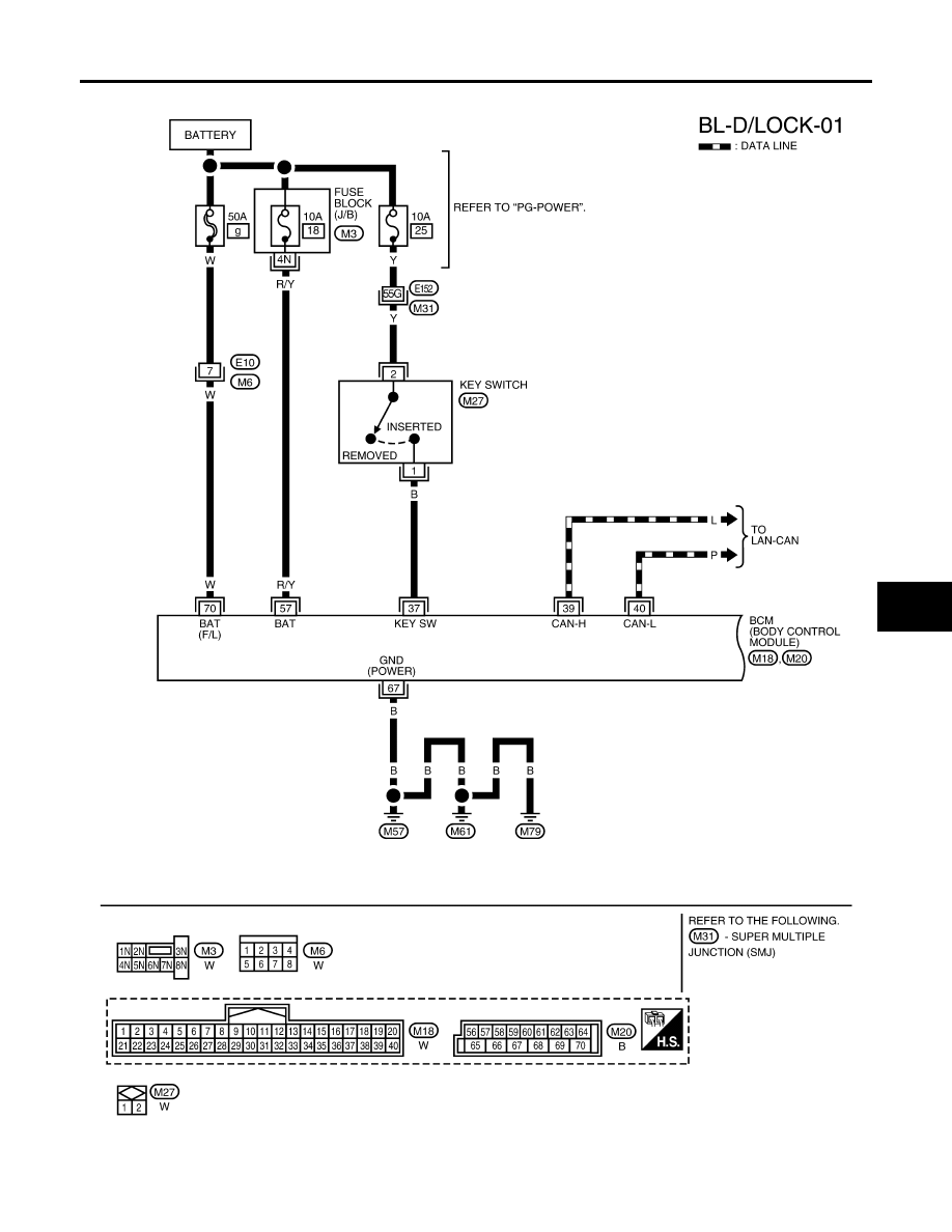
POWER DOOR LOCK SYSTEM
BL-21
C
D
E
F
G
H
J
K
L
M
A
B
BL
2007 Pathfinder
Wiring Diagram — D/LOCK —
EIS007OH
WIWA2134E
|
|
|
POWER DOOR LOCK SYSTEM BL-21 C D E F G H J K L M A B BL 2007 Pathfinder Wiring Diagram — D/LOCK — EIS007OH WIWA2134E |