Index Manuals Nissan Pathfinder (2007 year) - Service and Repair Manual
Search copyright infringement
Content .. 73 74 75 76 ..
Nissan Pathfinder (2007 year). Manual - part 75
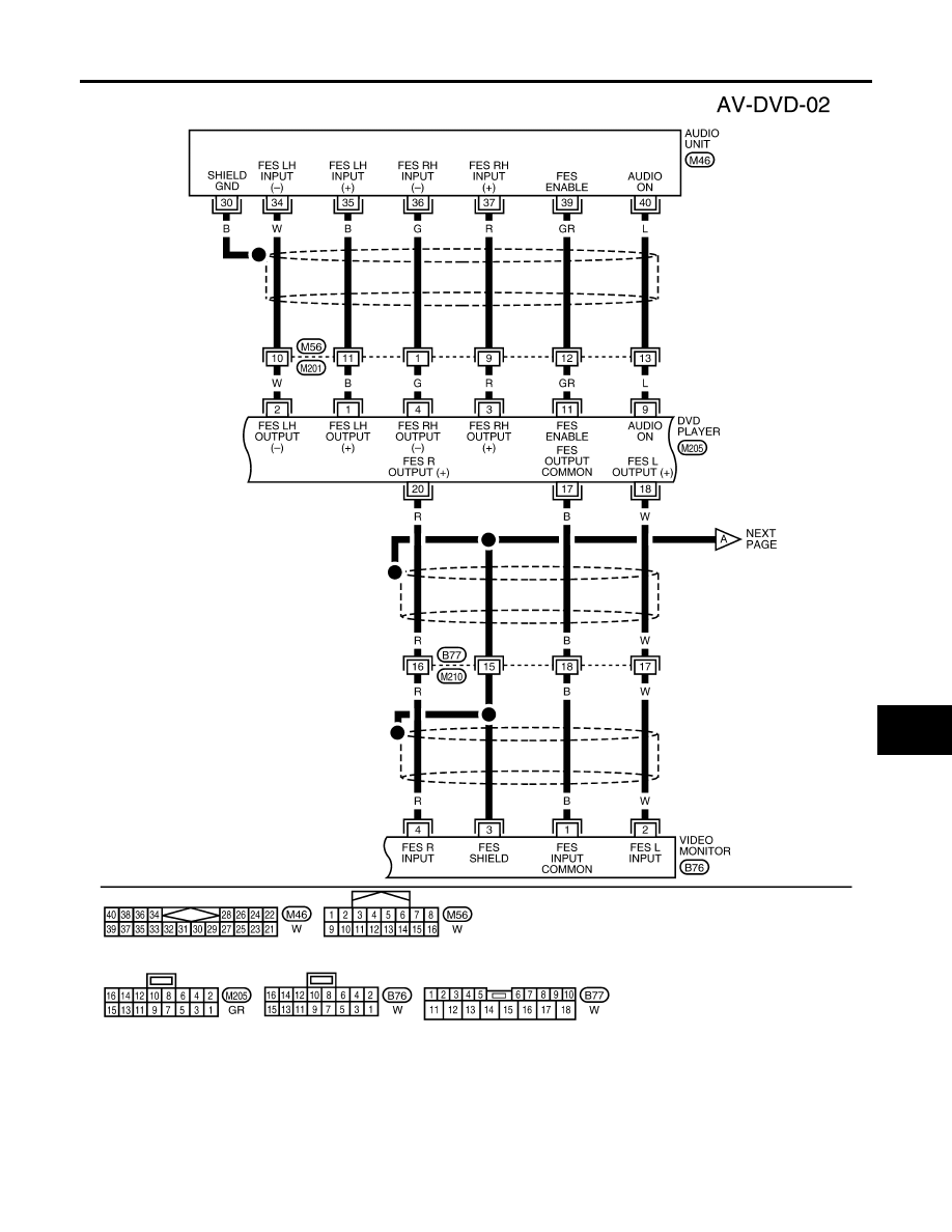
DVD ENTERTAINMENT SYSTEM
AV-73
C
D
E
F
G
H
I
J
L
M
A
B
AV
2007 Pathfinder
WKWA2002E