Nissan Pathfinder (2007 year). Manual - part 52


  Index      Manuals     Nissan Pathfinder (2007 year) - Service and Repair Manual


Search            copyright infringement  


Content      ..     50      51      52      53     ..


Nissan Pathfinder (2007 year). Manual - part 52


TROUBLE DIAGNOSIS

ATC-67

C

D

E

F

G

H

I

K

L

M

A

B

ATC

2007 Pathfinder

2. 

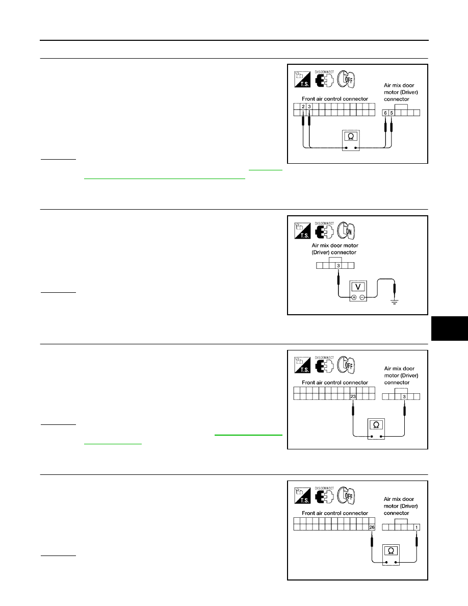
CHECK POWER SUPPLY CIRCUITS FOR AIR MIX DOOR MOTOR (DRIVER)

1.

Turn ignition switch OFF.

2.

Disconnect front air control connector and air mix door motor
(driver) connector.

3.

Check continuity between front air control harness connector
M49 terminal 2 and 3 and air mix door motor (driver) harness
connector M147 terminal 5 and 6.

OK or NG

OK

>> Replace air mix door motor (driver). Refer to 

ATC-149,

"FRONT AIR MIX DOOR MOTOR (DRIVER)"

 .

NG

>> Repair or replace harness as necessary.

3. 

CHECK PBR REFERENCE SIGNAL VOLTAGE

1.

Turn ignition switch OFF.

2.

Disconnect the air mix door motor (driver) connector.

3.

Turn ignition switch ON.

4.

Check voltage between air mix door motor (driver) harness con-
nector M147 terminal 3 and ground.

OK or NG

OK

>> GO TO 5.

NG

>> GO TO 4.

4. 

CHECK PBR REFERENCE VOLTAGE CIRCUIT BETWEEN AIR MIX DOOR MOTOR (DRIVER) AND 

FRONT AIR CONTROL

1.

Turn ignition switch OFF.

2.

Disconnect the front air control connector.

3.

Check continuity between air mix door motor (driver) harness
connector M147 terminal 3 and front air control harness connec-
tor M49 terminal 23.

OK or NG

OK

>> Replace front air control. Refer to 

ATC-131, "FRONT

AIR CONTROL"

 .

NG

>> Repair or replace harness as necessary.

5. 

CHECK PBR GROUND REFERENCE CIRCUIT 

1.

Turn ignition switch OFF.

2.

Disconnect the front air control connector.

3.

Check continuity between air mix door motor (driver) harness
connector M147 terminal 1 and front air control harness connec-
tor M49 terminal 26.

OK or NG

OK

>> GO TO 6.

NG

>> Repair or replace harness as necessary.

2 - 5

: Continuity should exist.

3 - 6

: Continuity should exist.

WJIA1092E

 3 - Ground

: Approx. 5V

WJIA1246E

3 - 23

: Continuity should exist.

WJIA1093E

1 - 26

: Continuity should exist.

WJIA1247E

ATC-68

TROUBLE DIAGNOSIS

2007 Pathfinder

6. 

CHECK PBR FEEDBACK SIGNAL

1.

Reconnect the front air control connector and air mix door motor
(driver) connector.

2.

Turn ignition switch ON.

3.

Check voltage between front air control harness connector M49
terminal 22 and ground.

4.

Rotate driver temperature control dial through complete range.

OK or NG

OK

>> Replace front air control. Refer to 

ATC-131, "FRONT

AIR CONTROL"

 .

NG

>> GO TO 7.

7. 

CHECK PBR FEEDBACK CIRCUIT

1.

Turn ignition switch OFF.

2.

Disconnect the air mix door motor (driver) connector and front
air control connector.

3.

Check continuity between air mix door motor (driver) harness
connector M147 terminal 2 and front air control harness connec-
tor M49 terminal 22.

OK or NG

OK

>> Replace air mix door motor (driver). Refer to 

ATC-149,

"FRONT AIR MIX DOOR MOTOR (DRIVER)"

 .

NG

>> Repair or replace harness as necessary.

DIAGNOSTIC PROCEDURE FOR AIR MIX DOOR MOTOR (PASSENGER)

1. 

CHECK RESULT FROM FRONT AIR CONTROL SELF-DIAGNOSIS 

Perform A/C system self-diagnosIs. Refer to 

ATC-50, "A/C System Self-diagnosis Function"

 .

Is self-diagnosis code 22 present?

YES

>> GO TO 2.

NO

>> GO TO 3.

2. 

CHECK POWER SUPPLY CIRCUIT FOR AIR MIX DOOR MOTOR (PASSENGER)

1.

Turn ignition switch OFF.

2.

Disconnect front air control connector and air mix door motor
(passenger) connector.

3.

Check continuity between front air control harness connector
M49 terminal 15 and 16 and air mix door motor (passenger) har-
ness connector M143 terminal 6 and 5.

OK or NG

OK

>> Replace air mix door motor (passenger). Refer to 

ATC-

149, "FRONT AIR MIX DOOR MOTOR (PASSENGER)"

.

NG

>> Repair or replace harness as necessary.

22 - Ground

: Approx. 0V - 5V

WJIA1096E

2 - 22

Continuity should exist.

WJIA1248E

15 - 6

Continuity should exist.

16 - 5

Continuity should exist.

WJIA1097E

TROUBLE DIAGNOSIS

ATC-69

C

D

E

F

G

H

I

K

L

M

A

B

ATC

2007 Pathfinder

3. 

CHECK PBR REFERENCE SIGNAL VOLTAGE

1.

Turn ignition switch OFF.

2.

Disconnect the air mix door motor (passenger) connector.

3.

Turn ignition switch ON.

4.

Check voltage between air mix door motor (passenger) harness
connector M143 terminal 1 and ground.

OK or NG

OK

>> GO TO 5.

NG

>> GO TO 4.

4. 

CHECK PBR REFERENCE VOLTAGE CIRCUIT BETWEEN AIR MIX DOOR (PASSENGER) AND 

FRONT AIR CONTROL

1.

Turn ignition switch OFF.

2.

Disconnect the front air control connector.

3.

Check continuity between air mix door motor (passenger) har-
ness connector M143 (B) terminal 1 and front air control harness
connector M49 (A) terminal 23.

OK or NG

OK

>> Replace front air control. Refer to 

ATC-131, "FRONT AIR CONTROL"

 .

NG

>> Repair or replace harness as necessary.

5. 

CHECK PBR GROUND REFERENCE CIRCUIT 

1.

Turn ignition switch OFF.

2.

Disconnect the front air control connector.

3.

Check continuity between air mix door motor (passenger) har-
ness connector M143 (B) terminal 3 and front air control harness
connector M49 (A) terminal 26.

OK or NG

OK

>> GO TO 6.

NG

>> Repair or replace harness as necessary.

Terminals

Condition

Voltage

(Approx.)

(+)

(-)

Air mix door motor 

(passenger) con-

nector

Terminal No.

M143

1

Ground

Air mix door 
(passenger)

5V

WJIA1682E

A

B

Connector

Terminal Connector

Terminal 

Continuity

Front air control: 

M49

23 

Air mix door motor 

(passenger): 

M143

1

Yes

WJIA1656E

A

B

Connector

Terminal Connector

Terminal 

Continuity

Front air control: 

M49

26 

Air mix door motor 

(passenger): 

M143

3

Yes

WJIA1650E

ATC-70

TROUBLE DIAGNOSIS

2007 Pathfinder

6. 

CHECK PBR FEEDBACK SIGNAL

1.

Reconnect the front air control connector and air mix door motor
(passenger) connector.

2.

Turn ignition switch ON.

3.

Check voltage between front air control harness connector M50
terminal 36 and ground.

4.

Rotate passenger temperature control dial through complete
range.

OK or NG

OK

>> Replace front air control. Refer to 

ATC-131, "FRONT

AIR CONTROL"

 .

NG

>> GO TO 7.

7. 

CHECK PBR FEEDBACK CIRCUIT

1.

Turn ignition switch OFF.

2.

Disconnect the air mix door motor (passenger) connector and
front air control connector.

3.

Check continuity between air mix door motor (passenger) har-
ness connector M143 terminal 2 and front air control harness
connector M50 terminal 36.

OK or NG

OK

>> Replace air mix door motor (passenger). Refer to 

ATC-

149, "FRONT AIR MIX DOOR MOTOR (PASSENGER)"

.

NG

>> Repair or replace harness as necessary.

DIAGNOSTIC PROCEDURE FOR AIR MIX DOOR MOTOR (REAR)

1. 

CHECK RESULT FROM FRONT AIR CONTROL SELF-DIAGNOSIS 

Perform A/C system self-diagnosIs. Refer to 

ATC-50, "A/C System Self-diagnosis Function"

 .

Is self-diagnosis code 38 present?

YES

>> GO TO 2.

NO

>> GO TO 3.

2. 

CHECK POWER SUPPLY CIRCUIT FOR AIR MIX DOOR MOTOR (REAR)

1.

Turn ignition switch OFF.

2.

Disconnect front air control connector and air mix door motor
(rear) connector.

3.

Check continuity between front air control harness connector
M49 terminal 17 and air mix door motor (rear) harness connec-
tor B155 terminal 6 and between front air control harness con-
nector M49 terminal 18 and air mix door motor (rear) harness
connector B155 terminal 1.

OK or NG

OK

>> Replace air mix door motor (rear). Refer to 

ATC-150, "REAR AIR MIX DOOR MOTOR"

 .

NG

>> Repair or replace harness as necessary.

36 - Ground

: Approx. 0 - 5V

WJIA1249E

2 - 36

: Continuity should exist.

WJIA1101E

17 - 6

Continuity should exist.

18 - 1

Continuity should exist.

WJIA1102E

TROUBLE DIAGNOSIS

ATC-71

C

D

E

F

G

H

I

K

L

M

A

B

ATC

2007 Pathfinder

3. 

CHECK PBR REFERENCE SIGNAL VOLTAGE

1.

Turn ignition switch OFF.

2.

Disconnect the air mix door motor (rear) connector.

3.

Turn ignition switch ON.

4.

Check voltage between air mix door motor (rear) harness con-
nector B155 terminal 3 and ground.

OK or NG

OK

>> GO TO 5.

NG

>> GO TO 4.

4. 

CHECK PBR REFERENCE VOLTAGE CIRCUIT BETWEEN AIR MIX DOOR MOTOR (REAR) AND 

FRONT AIR CONTROL

1.

Turn ignition switch OFF.

2.

Disconnect the front air control connector.

3.

Check continuity between air mix door motor (rear) harness con-
nector B155 terminal 3 and front air control harness connector
M49 terminal 23.

OK or NG

OK

>> Replace front air control. Refer to 

ATC-131, "FRONT

AIR CONTROL"

 .

NG

>> Repair or replace harness as necessary.

5. 

CHECK PBR GROUND REFERENCE CIRCUIT 

1.

Turn ignition switch OFF.

2.

Disconnect the front air control connector.

3.

Check continuity between air mix door motor (rear) harness con-
nector B155 terminal 2 and front air control harness connector
M49 terminal 26.

OK or NG

OK

>> GO TO 6.

NG

>> Repair or replace harness as necessary.

6. 

CHECK PBR FEEDBACK SIGNAL

1.

Reconnect the front air control connector and air mix door motor
(rear) connector.

2.

Turn ignition switch ON.

3.

Check voltage between front air control harness connector M49
terminal 25 and ground.

4.

Rotate rear temperature and mode control dial through complete
range.

OK or NG

OK

>> Replace front air control. Refer to 

ATC-131, "FRONT

AIR CONTROL"

 .

NG

>> GO TO 7.

3 - Ground

: Approx. 5V

LJIA0050E

3 - 23

Continuity should exist.

WJIA1103E

2 - 26

Continuity should exist.

WJIA1104E

25 - Ground

: Approx. 0 - 5V

WJIA1105E

ATC-72

TROUBLE DIAGNOSIS

2007 Pathfinder

7. 

CHECK PBR FEEDBACK CIRCUIT

1.

Turn ignition switch OFF.

2.

Disconnect the air mix door motor (rear) connector and front air
control connector.

3.

Check continuity between air mix door motor (rear) harness con-
nector B155 terminal 4 and front air control harness connector
M49 terminal 25.

OK or NG

OK

>> Replace air mix door motor (rear). Refer to 

ATC-150,

"REAR AIR MIX DOOR MOTOR"

 .

NG

>> Repair or replace harness as necessary.

4 - 25

Continuity should exist.

WJIA1106E

TROUBLE DIAGNOSIS

ATC-73

C

D

E

F

G

H

I

K

L

M

A

B

ATC

2007 Pathfinder

Intake Door Motor Circuit

EJS004P7

SYMPTOM:

Intake door does not change.

Intake door motor does not operate normally.

INSPECTION FLOW

1. 

CONFIRM SYMPTOM BY PERFORMING OPERATIONAL CHECK - REC (

)

1.

Press the mode switch to panel mode(

).

2.

Press REC (

) switch. The REC (

) indicator should illuminate.

3.

Press REC (

) switch again. The REC (

) indicator should go out.

4.

Listen for intake door position change (you should hear blower sound change slightly).

Can a symptom be duplicated?

YES

>> GO TO 3.

NO

>> GO TO 2.

2. 

PERFORM COMPLETE OPERATIONAL CHECK

Perform a complete operational check and check for any symptoms. Refer to 

ATC-52, "Operational Check

(Front)"

  .

Can a symptom be duplicated?

YES

>> Refer to 

ATC-34, "SYMPTOM TABLE"

 .

NO

>> System OK.

3. 

CHECK FOR SERVICE BULLETINS

Check for any service bulletins.

>> GO TO 4.

4. 

CHECK INTAKE DOOR OPERATION

Check and verify intake door mechanism for smooth operation. 

OK or NG

OK

>> GO TO 5. 

NG

>> Repair intake door mechanism.

5. 

PERFORM SELF-DIAGNOSIS

Perform self-diagnosis to check for any codes. Refer to 

ATC-50, "A/C System Self-diagnosis Function"

  .

Are any self-diagnosis codes present?

YES

>> Refer to 

ATC-51, "SELF-DIAGNOSIS CODE CHART"

  .

NO

>> GO TO 6.

6. 

RECHECK FOR ANY SYMPTOMS 

Perform a complete operational check for any symptoms. Refer to 

ATC-52, "Operational Check (Front)"

  .

Does another symptom exist?

YES

>> Refer to 

ATC-34, "SYMPTOM TABLE"

 . 

NO

>> Replace front air control. Refer to 

ATC-131, "FRONT AIR CONTROL"

 .

ATC-74

TROUBLE DIAGNOSIS

2007 Pathfinder

SYSTEM DESCRIPTION
Component Parts

Intake door control system components are:

Front air control

Intake door motor

In-vehicle sensor

Ambient sensor

Optical sensor

Intake sensor

System Operation

The intake door control determines the intake door position based on the position of the recirculation switch.
When the recirculation switch is depressed the intake door motor rotates closing off the fresh air inlet and
recirculating the cabin air. If the recirculation switch is depressed again, the intake door motor rotates in the
opposite direction, again allowing fresh air into the cabin.
In the AUTO mode, the front air control determines the intake door position based on the ambient tempera-
ture, the intake air temperature and the in-vehicle temperature. When the DEFROST, or OFF switches are
pushed or A/C switch is OFF, the front air control sets the intake door at the fresh position.

Intake Door Control Specification

WJIA1352E

WJIA0436E


Content      ..     50      51      52      53     ..