Nissan Pathfinder (2007 year). Manual - part 42


  Index      Manuals     Nissan Pathfinder (2007 year) - Service and Repair Manual


Search            copyright infringement  


Content      ..     40      41      42      43     ..


Nissan Pathfinder (2007 year). Manual - part 42


ASSEMBLY

AT-307

D

E

F

G

H

I

J

K

L

M

A

B

AT

2007 Pathfinder

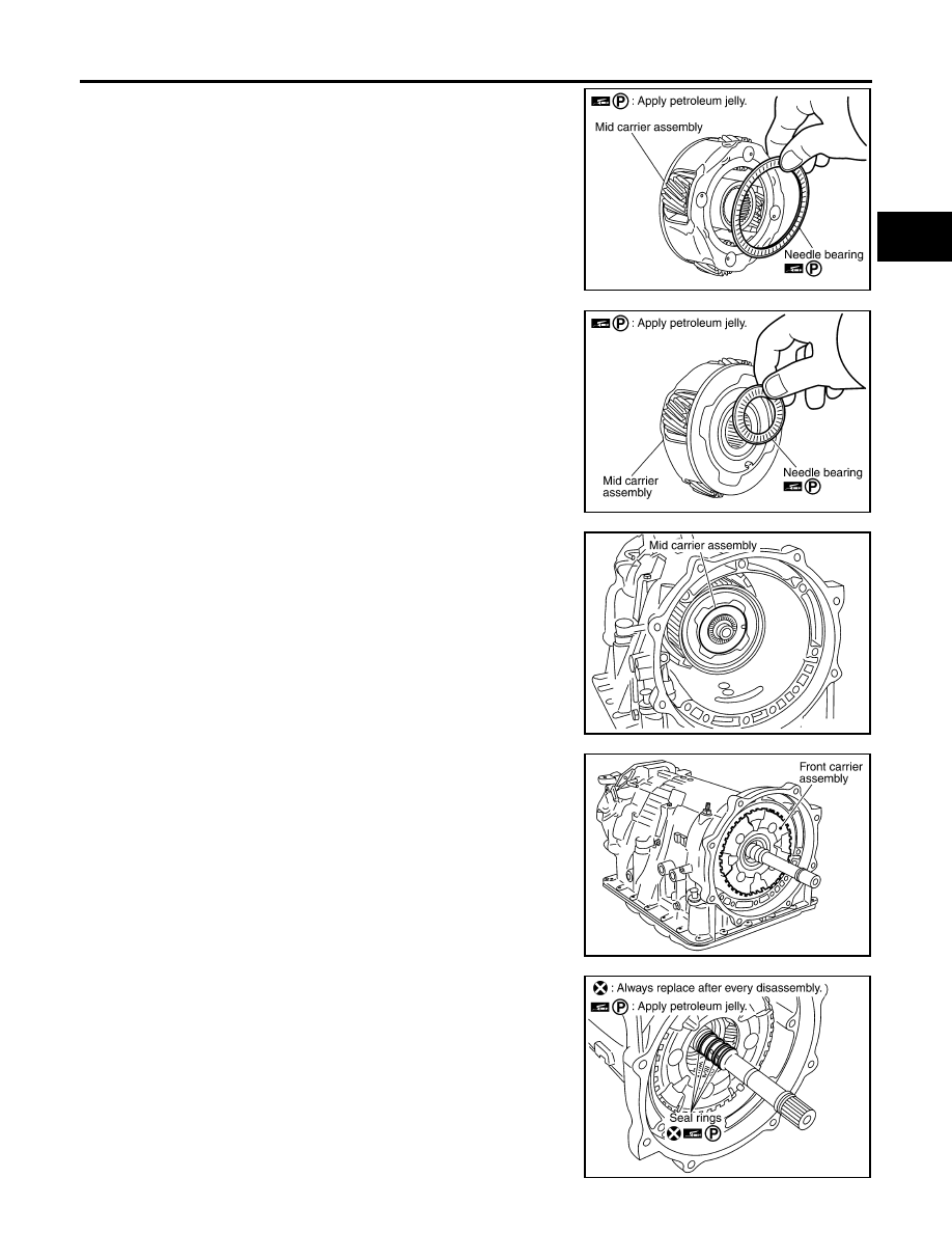
43. Install needle bearing (rear side) to mid carrier assembly.

CAUTION:

Apply petroleum jelly to needle bearing.

44. Install needle bearing (front side) to mid carrier assembly.

CAUTION:

Apply petroleum jelly to needle bearing.

45. Install mid carrier assembly in rear carrier assembly.

46. Install front carrier assembly, input clutch assembly and rear

internal gear as a unit.

47. Install seal rings in input clutch assembly.

CAUTION:

Do not reuse seal rings.

Apply petroleum jelly to seal rings.

SCIA2804E

SCIA2805E

SCIA5017E

SCIA5015E

SCIA2470E

AT-308

ASSEMBLY

2007 Pathfinder

48. Install band servo anchor end pin and lock nut in transmission

case.

CAUTION:

Do not reuse band servo anchor end pin.

49. Install brake band in transmission case.

CAUTION:

Install it so that the identification to avoid incorrect installa-
tion faces the servo side.

50. Install front sun gear to front carrier assembly.

CAUTION:

Apply ATF to front sun gear bearing and 3rd one-way clutch
end bearing.

51. Install needle bearing to front sun gear.

CAUTION:

Apply petroleum jelly to needle bearing.

52. Adjust brake band tilting using a clip so that brake band contacts

front sun gear drum evenly.

SCIA6512E

SCIA5498E

SCIA5014E

SCIA2808E

SCIA5033E

ASSEMBLY

AT-309

D

E

F

G

H

I

J

K

L

M

A

B

AT

2007 Pathfinder

53. Adjust brake band.

a.

Loosen lock nut.

b.

Tighten band servo anchor end pin to specified torque.

c.

Back off band servo anchor end pin three turns.

d.

Holding band servo anchor end pin, tighten lock nut to specified
torque.

Adjustment

ECS00EMA

TOTAL END PLAY

Measure clearance between front sun gear and bearing race for
oil pump cover.

Select proper thickness of bearing race so that end play is within
specifications.

1.

Measure dimensions “K” and “L” and then calculate dimension
“J”.

a.

Measure dimension “K”.

Anchor end pin

: 5.0 N·m (0.51 kg-m, 44 in-lb)

Lock nut

: 46 N·m (4.7 kg-m, 34 ft-lb)

SCIA5498E

SCIA2810E

SCIA5350E

SCIA5351E

AT-310

ASSEMBLY

2007 Pathfinder

b.

Measure dimension “L”.

c.

Calculate dimension “J”.

2.

Measure dimensions “M

1

 ” and “M

2

 ” and then calculate dimen-

sion “M”.

a.

Place bearing race and needle bearing on oil pump assembly.

b.

Measure dimension “M

1

 ”.

c.

Measure dimension “M

2

 ”.

“J”: Distance between oil pump fitting surface of 
transmission case and needle bearing mating surface 
of front sun gear.

J = K – L

SCIA5352E

SCIA3125E

SCIA3124E

SCIA3126E

SCIA3127E

ASSEMBLY

AT-311

D

E

F

G

H

I

J

K

L

M

A

B

AT

2007 Pathfinder

d.

Calculate dimension “M”.

3.

Adjust total end play “T

1

 ”.

Select proper thickness of bearing race so that total end play
is within specifications.

Assembly (2)

ECS00EMB

1.

Install O-ring to oil pump assembly.

CAUTION:

Do not reuse O-ring.

Apply ATF to O-ring.

2.

Install bearing race to oil pump assembly.

CAUTION:

Apply petroleum jelly to bearing race.

“M”: Distance between transmission case fitting sur-
face of oil pump and needle bearing on oil pump.

M = M

1

  – M

2

SCIA3125E

T

1

  = J – M

Total end play “T

1


: 0.25 - 0.55 mm (0.0098 - 0.0217 in)

Bearing races

:Refer to 

AT-320, "BEARING RACE 

FOR ADJUSTING TOTAL END PLAY"

 .

SCIA2810E

SCIA5172E

SCIA6529E

AT-312

ASSEMBLY

2007 Pathfinder

3.

Install oil pump assembly in transmission case.

CAUTION:

Apply ATF to oil pump bearing.

4.

Apply recommended sealant (Genuine RTV Silicone Sealant or
equivalent. Refer to 

GI-47, "Recommended Chemical Products

and Sealants"

 .) to oil pump assembly as shown.

CAUTION:

Completely remove all moisture, oil, old sealant and any
foreign material from the oil pump bolts and oil pump bolt
mating surfaces.

5.

Tighten oil pump bolts to specified torque.

CAUTION:

Apply ATF to oil pump bushing.

6.

Install O-ring to input clutch assembly.

CAUTION:

Do not reuse O-ring.

Apply ATF to O-ring.

7.

Install converter housing to transmission case and tighten bolts
to specified torque.

CAUTION:

Do not reuse self-sealing bolt (A).

SCIA2811E

SCIA5321E

Oil pump bolts

: 48 N·m (4.9 kg-m, 35 ft-lb)

SCIA2300E

SCIA5011E

Converter housing bolt

: 52 N·m (5.3 kg-m, 38 ft-lb)

Self-sealing bolt (A)

: 61 N·m (6.2 kg-m, 45 ft-lb)

WCIA0662E

ASSEMBLY

AT-313

D

E

F

G

H

I

J

K

L

M

A

B

AT

2007 Pathfinder

8.

Make sure that brake band does not close turbine revolution
sensor hole.

9.

Install control valve with TCM.

a.

Connect TCM connector and park/neutral position switch con-
nector.

b.

Install A/T assembly harness connector to control valve with
TCM.

c.

Connect TCM connectors.

SCIA5034E

SCIA5449E

SCIA5450E

SCIA5447E

AT-314

ASSEMBLY

2007 Pathfinder

d.

Install O-ring to A/T assembly harness connector.

CAUTION:

Do not reuse O-ring.

Apply ATF to O-ring.

e.

Install A/T fluid temperature sensor 2 to bracket.

f.

Install A/T fluid temperature sensor 2 (with bracket) to control
valve with TCM and tighten bolt to specified torque.

CAUTION:

Adjust bolt hole of bracket to bolt hole of control valve.

g.

Install control valve with TCM in transmission case.

CAUTION:

Make sure that turbine revolution sensor is securely
installed into turbine revolution sensor hole.

Hang down revolution sensor harness toward outside so
as not to disturb installation of control valve with TCM.

Adjust A/T assembly harness connector of control valve
with TCM to terminal hole of transmission case.

Assemble it so that manual valve cutout is engaged with
manual plate projection.

SCIA5155E

SCIA5264E

Bracket bolt

: 7.9 N·m (0.81 kg-m, 70 in-lb)

SCIA5301E

SCIA5034E

SCIA5035E


Content      ..     40      41      42      43     ..