Nissan Pathfinder (2006 year). Manual - part 378
AUTOMATIC DRIVE POSITIONER
SE-29
C
D
E
F
G
H
J
K
L
M
A
B
SE
2006 Pathfinder
17
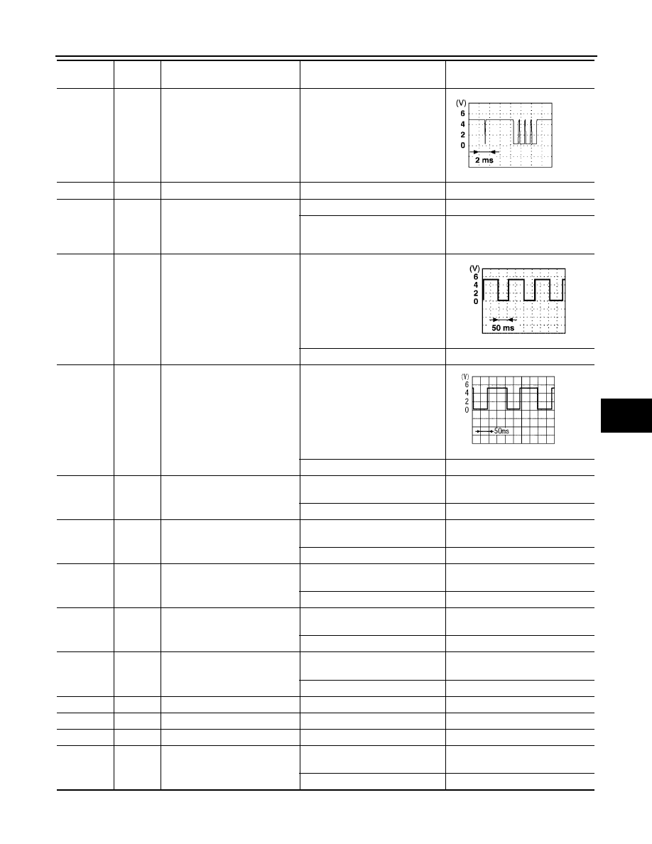
R/W
UART LINE (TX)
Pedal adjusting switch ON (FOR-
WARD or BACKWARD operation)
19
P
CAN-L
—
—
21
L
A/T device (park position switch)
signal
A/T selector lever in P position
0
A/T selector lever in other than P
position with ignition key in ignition
cylinder
Battery voltage
24
Y/G
Seat sliding motor sensor signal
ON (seat sliding motor operation)
Other than above
0 or 5
25
LG
Front lifting motor sensor signal
ON (front lifting motor operation)
Other than above.
0 or 5
26
P/B
Seat sliding switch FORWARD
signal
ON (seat sliding switch FOR-
WARD operation)
0
Other than above
Battery voltage
27
G/B
Seat reclining switch FOR-
WARD signal
ON (seat reclining switch FOR-
WARD operation)
0
Other than above
Battery voltage
28
Y/B
Front lifting switch UP signal
ON (front lifting switch UP opera-
tion)
0
Other than above
Battery voltage
29
R/W
Rear lifting switch UP signal
ON (rear lifting switch UP opera-
tion)
0
Other than above
Battery voltage
30
L/W
Pedal adjusting switch FOR-
WARD signal
ON (pedal adjusting switch FOR-
WARD operation)
0
Other than above
Battery voltage
31
L/Y
Sensor ground
—
0
32
B
Ground
—
0
33
W/L
Battery power supply (PTC)
—
Battery voltage
35
V/W
Sliding motor FORWARD out-
put signal
Sliding switch FORWARD opera-
tion (Motor operated)
Battery voltage
Other than above
0
Terminal
Wire
Color
Item
Condition
Voltage (V)
(Approx.)
PIIA4814E
PIIA3277E
SIIA0691J