Nissan Pathfinder (2006 year). Manual - part 340
TROUBLE DIAGNOSIS
MTC-73
C
D
E
F
G
H
I
K
L
M
A
B
MTC
2006 Pathfinder
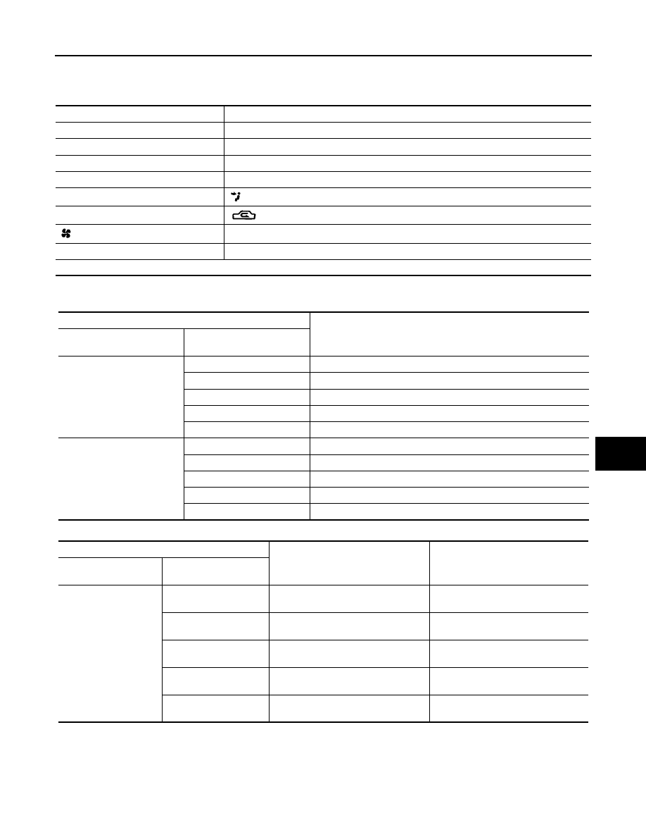
PERFORMANCE CHART
Test Condition
Testing must be performed as follows:
Test Reading
Recirculating-to-discharge Air Temperature Table
Ambient Air Temperature-to-operating Pressure Table
Vehicle location
Indoors or in the shade (in a well-ventilated place)
Doors
Closed
Door window
Open
Hood
Open
TEMP.
Max. COLD
Mode switch
(Ventilation) set
Recirculation (REC) switch
(Recirculation) set
Blower speed
Max. speed set
Engine speed
Idle speed
Operate the air conditioning system for 10 minutes before taking measurements.
Inside air (Recirculating air) at blower assembly inlet
Discharge air temperature at center ventilator
°
C (
°
F)
Relative humidity
%
Air temperature
°
C (
°
F)
50 - 60
20 (68)
5.3 - 6.5 (42 - 44)
25 (77)
9.7 - 11.5 (49 - 53)
30 (86)
13.8 - 16.3 (57 - 61)
35 (95)
18.0 - 21.2 (64 - 70)
40 (104)
22.2 - 25.7 (72 - 78)
60 - 70
20 (68)
6.5 - 7.7 (44 - 46)
25 (77)
11.5 - 13.3 (53 - 56)
30 (86)
16.3 - 18.8 (61 - 66)
35 (95)
21.2 - 24.0 (70 - 75)
40 (104)
25.7 - 29.2 (78 - 85)
Ambient air
High-pressure (Discharge side)
kPa (kg/cm
2
, psi)
Low-pressure (Suction side)
kPa (kg/cm
2
, psi)
Relative humidity
%
Air temperature
°
C (
°
F)
50 - 70
20 (68)
680 - 840
(6.94 - 8.57, 98.6 - 121.8)
160 - 198
(1.63 - 2.02, 23.2 - 28.7)
25 (77)
800 - 985
(8.16 - 10.05, 116.0 - 142.8)
198 - 245
(2.02 - 2.50, 28.7 - 35.5)
30 (86)
940 - 1,150
(9.59 - 11.73, 136.3 - 166.8)
225 - 278
(2.30 - 2.84, 32.6 - 40.3)
35 (95)
1,160 - 1,410
(11.83 - 14.38, 168.2 - 204.5)
273 - 335
(2.78 - 3.42, 39.6 - 48.6)
40 (104)
1,325 - 1,620
(13.52 - 16.52, 192.1 - 234.9)
325 - 398
(3.32 - 4.06, 47.1 - 57.7)