Nissan Pathfinder (2006 year). Manual - part 341


  Index      Manuals     Nissan Pathfinder (2006 year) - Service and Repair Manual


Search            copyright infringement  


Content      ..     339      340      341      342     ..


Nissan Pathfinder (2006 year). Manual - part 341


TROUBLE DIAGNOSIS

MTC-81

C

D

E

F

G

H

I

K

L

M

A

B

MTC

2006 Pathfinder

3. 

CHECK INTAKE SENSOR

Refer to 

ATC-126, "Intake Sensor"

 .

OK or NG

OK

>> Replace front air control. Refer to 

MTC-82, "FRONT AIR CONTROL"

 .

NG

>> Replace intake sensor. Refer to 

MTC-83, "INTAKE SENSOR"

 .

4. 

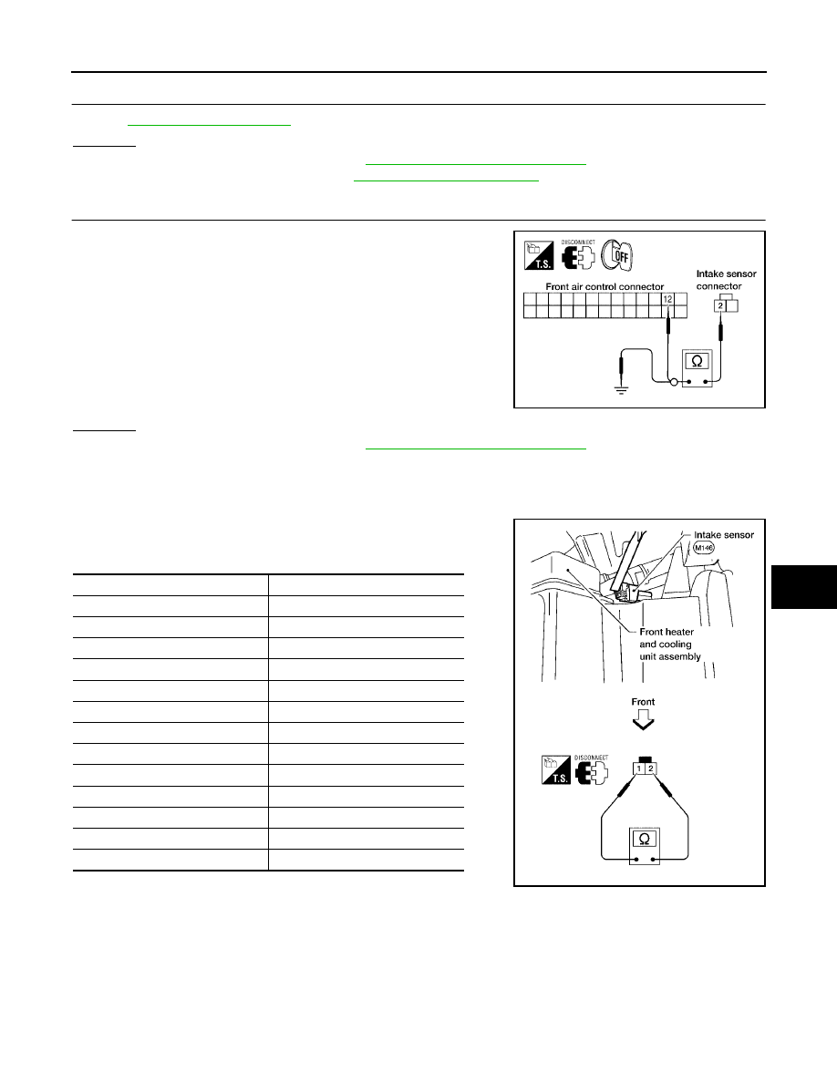
CHECK CIRCUIT CONTINUITY BETWEEN INTAKE SENSOR AND FRONT AIR CONTROL

1.

Turn ignition switch OFF.

2.

Disconnect front air control connector.

3.

Check continuity between intake sensor harness connector
M146 terminal 2 and front air control harness connector M49 ter-
minal 12.

4.

Check continuity between intake sensor harness connector
M146 terminal 2 and ground.

OK or NG

OK

>> Replace front air control. Refer to 

MTC-82, "FRONT AIR CONTROL"

 .

NG

>> Repair harness or connector.

COMPONENT INSPECTION
Intake Sensor

After disconnecting intake sensor connector, measure resistance
between terminals 1 and 2 at sensor harness side, using the table
below.

If NG, replace intake sensor.

2 - 12

: Continuity should exist.

2 - Ground

: Continuity should not exist.

WJIA1158E

Temperature 

°

C (

°

F)

Resistance k

15 (5)

209.0

10 (14)

160.0

5 (23)

123.0

0 (32)

95.8

5 (41)

74.9

10 (50)

58.9

15 (59)

46.7

20 (68)

37.3

25 (77)

30.0

30 (86)

24.2

35 (95)

19.7

40 (104)

16.1

45 (113)

13.2

WJIA1159E

MTC-82

CONTROL UNIT

2006 Pathfinder

CONTROL UNIT

PFP:27500

Removal and Installation

EJS004RW

FRONT AIR CONTROL
Removal

1.

Remove cluster lid C. Refer to 

IP-11, "CLUSTER LID C -WITH-

OUT NAVIGATION SYSTEM"

 .

2.

Remove the four screws securing the front air control to cluster
lid C.

3.

Remove the front air control.

Installation

Installation is in the reverse order of removal.

LBIA0416E

INTAKE SENSOR

MTC-83

C

D

E

F

G

H

I

K

L

M

A

B

MTC

2006 Pathfinder

INTAKE SENSOR

PFP:27723

Removal and Installation

EJS004RX

REMOVAL

1.

Remove the front kick plate. Refer to 

EI-28, "KICK PLATES"

 .

2.

Remove the lower dash side finisher. Refer to 

EI-28, "LOWER DASH SIDE FINISHER"

 .

3.

Remove the front pillar lower finisher. Refer to 

EI-28, "FRONT PILLAR LOWER FINISHER"

 .

4.

Remove the assist grip handle

5.

Remove the front pillar upper finisher. Refer to 

EI-28, "FRONT PILLAR UPPER FINISHER"

 .

6.

Remove the lower glove box. Refer to 

IP-15, "LOWER INSTRUMENT PANEL RH AND LOWER GLOVE

BOX"

 .

7.

Remove the upper glove box (cluster lid E). Refer to 

IP-10, "INSTRUMENT PANEL ASSEMBLY"

 .

8.

Disconnect the intake sensor electrical connector.
NOTE:
The intake sensor is located on the top of the heater and cooling
unit assembly next to the A/C evaporator cover.

9.

Twist the intake sensor to remove the intake sensor from the
heater and cooling unit assembly.

INSTALLATION

Installation is in the reverse order of removal.

WJIA1415E

MTC-84

BLOWER MOTOR

2006 Pathfinder

BLOWER MOTOR

PFP:27226

Components

EJS004RY

Blower Motor

Removal and Installation

EJS004RZ

REMOVAL

1.

Remove the lower glove box assembly. Refer to 

IP-15, "LOWER INSTRUMENT PANEL RH AND LOWER

GLOVE BOX"

 .

2.

Disconnect the blower motor electrical connector.

3.

Remove the three screws and remove the blower motor.

INSTALLATION

Installation is in the reverse order of removal.

LJIA0136E

1.

Heater and cooling unit assembly

2.

Blower motor

3.

Blower motor resistor

IN-CABIN MICROFILTER

MTC-85

C

D

E

F

G

H

I

K

L

M

A

B

MTC

2006 Pathfinder

IN-CABIN MICROFILTER

PFP:27277

Removal and Installation

EJS004S0

FUNCTION

The air inside the passenger compartment is filtered by the in-cabin
microfilters when the heater or A/C controls are set on either the
recirculation or fresh mode. The two in-cabin microfilters are located
in the heater and cooling unit assembly.

REPLACEMENT TIMING

Replacement of the two in-cabin microfilters is recommended on a regular interval depending on the driving
conditions. Refer to 

MA-7, "PERIODIC MAINTENANCE"

 . It may also be necessary to replace the two in-cabin

microfilters as part of a component replacement if the in-cabin microfilters are damaged.

REPLACEMENT PROCEDURE

1.

Open the lower glove box and press in on the sides so that it will
open completely allowing it to hang by the cord.

2.

Remove the screw and remove the in-cabin microfilter cover.

3.

Remove the in-cabin microfilters from the heater and cooling
unit housing.

4.

Insert the first new in-cabin microfilter into the heater and cool-
ing unit housing and slide it over to the right. Insert the second
new in-cabin microfilter into the heater and cooling unit housing.

NOTE:
The in-cabin microfilters are marked with air flow arrows. The
end of the microfilter with the arrow should face the rear of the
vehicle. The arrows should point downward.

LJIA0012E

WLIA0023E

LJIA0134E

LJIA0148E

MTC-86

IN-CABIN MICROFILTER

2006 Pathfinder

5.

Install the in-cabin microfilter cover.

6.

Close the lower glove box completely.

LJIA0134E

HEATER & COOLING UNIT ASSEMBLY

MTC-87

C

D

E

F

G

H

I

K

L

M

A

B

MTC

2006 Pathfinder

HEATER & COOLING UNIT ASSEMBLY

PFP:27110

Components

EJS004S1

Heater and Cooling Unit Assembly

Removal and Installation

EJS004S2

REMOVAL

1.

Discharge the refrigerant from the A/C system. Refer to 

ATC-154, "Discharging Refrigerant"

 .

2.

Drain the coolant from the engine cooling system. Refer to 

MA-13, "DRAINING ENGINE COOLANT"

 .

3.

Disconnect the battery negative and positive terminals.

WJIA1416E

1.

High-pressure A/C pipe

2.

Low-pressure A/C pipe

3.

Expansion valve

4.

Heater core and evaporator pipes 
grommet

5.

A/C drain hose grommet

6.

A/C drain hose

7.

Heater core pipe mounts

8.

Heater core pipes

9.

Heater and cooling unit assembly

MTC-88

HEATER & COOLING UNIT ASSEMBLY

2006 Pathfinder

4.

Remove the RH heater core pipes nut.

5.

Disconnect the heater core hoses from the heater core.

6.

Disconnect the high- and low-pressure A/C pipes from the
expansion valve.

7.

Move the two front seats to the rearmost position on the seat
track.

8.

Remove the instrument panel and console panel. Refer to 

IP-10,

"Removal and Installation"

 .

9.

Remove the two front floor ducts.

10. Remove the steering column. Refer to 

PS-10, "Removal and

Installation"

 .

11. Disconnect the instrument panel wire harness at the RH and LH in-line connector brackets, and the fuse

block (SMJ) electrical connectors. Refer to 

PG-43, "Harness Layout"

 .

12. Remove the covers then remove the three steering member bolts from each side to disconnect the steer-

ing member from the vehicle body.

13. Remove the heater and cooling unit assembly with it attached to the steering member, from the vehicle.

CAUTION:

Use care not to damage the seats and interior trim panels when removing the heater and cooling
unit assembly with it attached to the steering member.

Use suitable plugs on the heater core pipes to prevent coolant leakage.

14. Remove the heater and cooling unit assembly from the steering member.

INSTALLATION

Installation is in the reverse order of removal.

CAUTION:

Replace the O-ring of the low-pressure A/C pipe and high-pressure A/C pipe with a new one, and
apply compressor oil to the O-ring for installation. Refer to 

MTC-100, "Components"

 .

After charging the refrigerant, check for leaks. Refer to 

ATC-170, "Checking for Refrigerant Leaks"

.

NOTE:

Fill the engine cooling system with the specified coolant mixture. Refer to 

MA-14, "REFILLING ENGINE

COOLANT"

 .

Recharge the A/C system. Refer to 

ATC-154, "Evacuating System and Charging Refrigerant"

 .

WJIA1292E


Content      ..     339      340      341      342     ..