Nissan Pathfinder (2006 year). Manual - part 255
ON-VEHICLE SERVICE
FSU-7
C
D
F
G
H
I
J
K
L
M
A
B
FSU
2006 Pathfinder
●
Your alignment machine should be regularly calibrated in order to give correct information.
●
Check with the manufacturer of your specific alignment machine for their recommended Service/Cali-
bration Schedule.
THE ALIGNMENT PROCESS
IMPORTANT: Use only the alignment specifications listed in this Service Manual. Refer to
.
1.
When displaying the alignment settings, many alignment machines use “indicators”: (Green/red, plus or
minus, Go/No Go). Do NOT use these indicators.
●
The alignment specifications programmed into your alignment machine that operate these indicators
may not be correct.
●
This may result in an ERROR.
2.
Some newer alignment machines are equipped with an optional “Rolling Compensation” method to “com-
pensate” the sensors (alignment targets or head units). Do NOT use this “Rolling Compensation”
method.
●
Use the “Jacking Compensation” method. After installing the alignment targets or head units, raise the
vehicle and rotate the wheels 1/2 turn both ways.
●
See Instructions in the alignment machine you are using for more information.
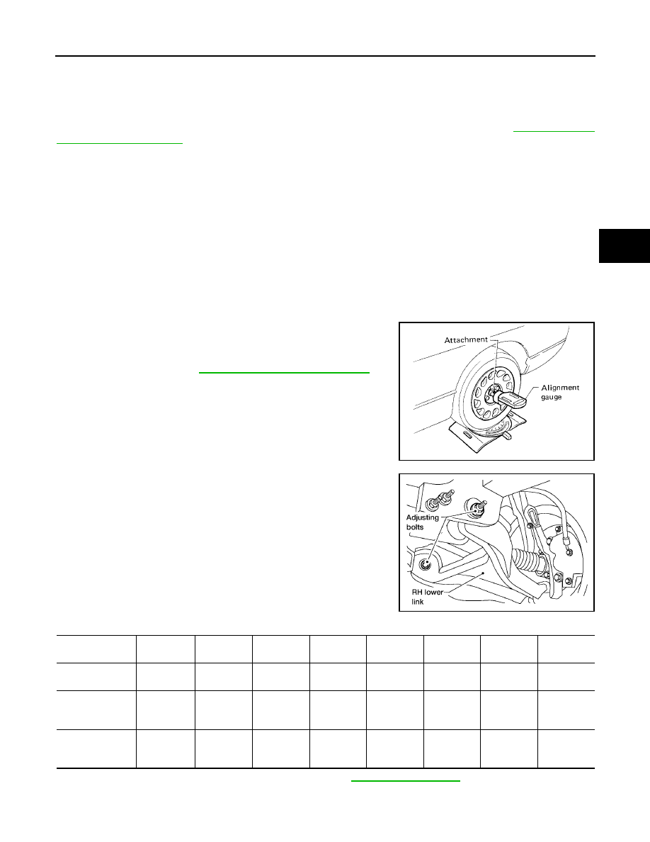
CAMBER AND CASTER
1.
Measure camber and caster of both the right and left wheels
with a suitable alignment gauge and adjust as necessary to
specification.
NOTE:
Some vehicles may be equipped with straight (non-adjustable)
lower link bolts and washers. In order to adjust camber and
caster on these vehicles, first replace the lower link bolts and
washers with adjustable (cam) bolts and washers.
2.
If outside of the specified value, adjust camber and caster using
the adjusting bolts in the front lower link.
CAUTION:
After adjusting the camber then check the toe-in.
NOTE:
Camber changes about 3' (0.05
°
) minutes with each graduation
of one adjusting bolt. Refer to table below for examples of lower
link adjusting bolt effect on camber and caster.
3.
Tighten the adjusting bolt nuts to specification. Refer to
Camber
: Refer to
FSU-6, "Front Wheel Alignment"
.
SRA096A
WEIA0115E
Rear adjusting
bolt
1 In
1 Out
1 In
1 Out
0
0
1 In
1 Out
Front adjusting
bolt
1 Out
1 In
1 In
1 Out
1 In
1 Out
0
0
Camber
Degree minute
(Decimal degree)
0 (0)
0 (0)
7' (0.12
°
)
- 7' (-0.12
°
)
3' (0.05
°
)
- 3' (-0.05
°
)
3' (0.05
°
)
- 3' (-0.05
°
)
Caster
Degree minute
(Decimal degree)
- 12' (-0.20
°
)
12' (0.20
°
)
0 (0)
0 (0)
6' (0.10
°
)
- 6' (-0.10
°
)
- 6' (-0.10
°
)
6' (0.10
°
)