Nissan Pathfinder (2006 year). Manual - part 220
DTC P2A00, P2A03 A/F SENSOR 1
EC-619
C
D
E
F
G
H
I
J
K
L
M
A
EC
2006 Pathfinder
11.
REPLACE A/F SENSOR 1
Replace A/F sensor 1.
CAUTION:
●
Discard any A/F sensor which has been dropped from a height of more than 0.5 m (19.7 in) onto a
hard surface such as a concrete floor; use a new one.
●
Before installing new A/F sensor, clean exhaust system threads using Heated Oxygen Sensor
Thread Cleaner tool J-43897-18 or J-43897-12 and approved anti-seize lubricant.
>> GO TO 12.
12.
CONFIRM A/F ADJUSTMENT DATA
1.
Turn ignition switch ON.
2.
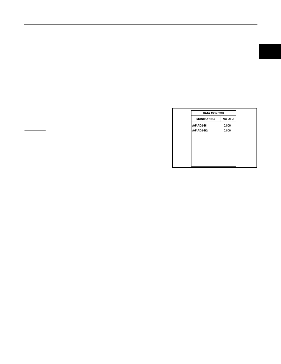
Select “A/F ADJ-B1” and “A/F ADJ-B2” in “DATA MONITOR”
mode with CONSULT-II.
3.
Make sure that “0” is displayed on CONSULT-II screen.
OK or NG
OK
>> INSPECTION END
NG
>> GO TO 13.
PBIB3202E