Nissan Pathfinder (2006 year). Manual - part 218


  Index      Manuals     Nissan Pathfinder (2006 year) - Service and Repair Manual


Search            copyright infringement  


Content      ..     216      217      218      219     ..


Nissan Pathfinder (2006 year). Manual - part 218


DTC P2138 APP SENSOR

EC-603

C

D

E

F

G

H

I

J

K

L

M

A

EC

2006 Pathfinder

DTC Confirmation Procedure

UBS00KHQ

NOTE:
If DTC Confirmation Procedure has been previously conducted, always turn ignition switch OFF and wait at
least 10 seconds before conducting the next test.
TESTING CONDITION:
Before performing the following procedure, confirm that battery voltage is more than 10V at idle.

 WITH CONSULT-II

1.

Turn ignition switch ON.

2.

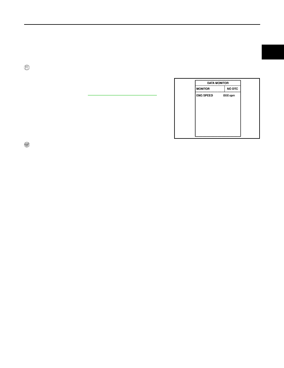
Select “DATA MONITOR” mode with CONSULT-II.

3.

Start engine and let it idle for 1 second.

4.

If DTC is detected, go to 

EC-605, "Diagnostic Procedure"

 .

 WITH GST

Follow the procedure “WITH CONSULT-II” above.

SEF058Y

EC-604

DTC P2138 APP SENSOR

2006 Pathfinder

Wiring Diagram

UBS00KHR

BBWA1749E

DTC P2138 APP SENSOR

EC-605

C

D

E

F

G

H

I

J

K

L

M

A

EC

2006 Pathfinder

Specification data are reference values and are measured between each terminal and ground.

CAUTION:

Do not use ECM ground terminals when measuring input/output voltage. Doing so may result in dam-
age to the ECM's transistor. Use a ground other than ECM terminals, such as the ground.

Diagnostic Procedure

UBS00KHS

1. 

CHECK GROUND CONNECTIONS

1.

Turn ignition switch OFF.

2.

Loosen and retighten three ground screws on the body. Refer to 

EC-151, "Ground Inspection"

 .

OK or NG

OK

>> GO TO 2.

NG

>> Repair or replace ground connections.

TER-

MINAL 

NO.

WIRE 

COLOR

ITEM

CONDITION

DATA (DC Voltage)

47

L

Sensor power supply 
(Throttle position sensor)

[Ignition switch: ON]

Approximately 5V

82

B

Sensor ground
(APP sensor 1)

[Engine is running]

Warm-up condition

Idle speed

Approximately 0V

83

GR

Sensor ground
(APP sensor 2)

[Engine is running]

Warm-up condition

Idle speed

Approximately 0V

90

L

Sensor power supply
(APP sensor 1)

[Ignition switch: ON]

Approximately 5V

91

G

Sensor power supply
(APP sensor 2)

[Ignition switch: ON]

Approximately 5V

98

GR

Accelerator pedal position 
sensor 2

[Ignition switch: ON]

Engine: Stopped

Accelerator pedal: Fully released

0.28 - 0.48V

[Ignition switch: ON]

Engine: Stopped

Accelerator pedal: Fully depressed

More than 2.0V

106

R

Accelerator pedal position 
sensor 1

[Ignition switch: ON]

Engine: Stopped

Accelerator pedal: Fully released

0.65 - 0.87V

[Ignition switch: ON]

Engine: Stopped

Accelerator pedal: Fully depressed

More than 4.3V

BBIA0539E

EC-606

DTC P2138 APP SENSOR

2006 Pathfinder

2. 

CHECK APP SENSOR 1 POWER SUPPLY CIRCUIT

1.

Disconnect accelerator pedal position (APP) sensor harness connector.

2.

Turn ignition switch ON.

3.

Check voltage between APP sensor terminals 2 and ground with
CONSULT-II or tester.

OK or NG

OK

>> GO TO 3.

NG

>> Repair open circuit or short to ground or short to power

in harness or connectors.

3. 

CHECK APP SENSOR 2 POWER SUPPLY CIRCUIT-I

Check voltage between APP sensor terminal 1 and ground with
CONSULT-II or tester. 

1.

OK or NG

OK

>> GO TO 8.

NG

>> GO TO 4.

4. 

CHECK APP SENSOR 2 POWER SUPPLY CIRCUIT-II

1.

Turn ignition switch OFF.

2.

Disconnect ECM harness connector.

3.

Check harness continuity between APP sensor terminal 1 and ECM terminal 91.
Refer to wiring diagram.

OK or NG

OK

>> GO TO 5.

NG

>> Repair open circuit.

Voltage: Approximately 5V

BBIA0556E

PBIB2608E

Voltage: Approximately 5V

PBIB2611E

Continuity should exist.

DTC P2138 APP SENSOR

EC-607

C

D

E

F

G

H

I

J

K

L

M

A

EC

2006 Pathfinder

5. 

CHECK APP SENSOR 2 POWER SUPPLY CIRCUIT-III

Check harness for short to power and short to ground, between the following terminals.

OK or NG

OK

>> GO TO 6.

NG

>> Repair open circuit or short to ground or short to power in harness or connectors.

6. 

CHECK THROTTLE POSITION SENSOR

Refer to 

EC-344, "Component Inspection"

 .

OK or NG

OK

>> GO TO 12.

NG

>> GO TO 7.

7. 

REPLACE ELECTRIC THROTTLE CONTROL ACTUATOR

1.

Replace electric throttle control actuator.

2.

Perfor

EC-77, "Throttle Valve Closed Position Learning"

 .

3.

Perfor

EC-77, "Idle Air Volume Learning"

 .

>> INSPECTION END

8. 

CHECK APP SENSOR GROUND CIRCUIT FOR OPEN AND SHORT

1.

Turn ignition switch OFF.

2.

Disconnect ECM harness connector.

3.

Check harness continuity between APP sensor terminals 4 and ECM terminal 82, APP sensor terminal 5
and ECM terminal 83.
Refer to Wiring Diagram.

4.

Also check harness for short to ground and short to power.

OK or NG

OK

>> GO TO 9.

NG

>> Repair open circuit or short to ground or short to power in harness or connectors.

9. 

CHECK APP SENSOR INPUT SIGNAL CIRCUIT FOR OPEN AND SHORT

1.

Check harness continuity between ECM terminal 106 and APP sensor terminal 3, ECM terminal 98 and
APP sensor terminal 6.
Refer to Wiring Diagram.

2.

Also check harness for short to ground and short to power.

OK or NG

OK

>> GO TO 10.

NG

>> Repair open circuit or short to ground or short to power in harness or connectors.

ECM terminal

Sensor terminal

Reference Wiring Diagram

91

APP sensor terminal 1

EC-590

47

Electric throttle control actuator terminal 2

EC-597

Continuity should exist.

Continuity should exist.

EC-608

DTC P2138 APP SENSOR

2006 Pathfinder

10. 

CHECK APP SENSOR

Refer to 

EC-608, "Component Inspection"

 .

OK or NG

OK

>> GO TO 12.

NG

>> GO TO 11.

11. 

REPLACE ACCELERATOR PEDAL ASSEMBLY

1.

Replace accelerator pedal assembly.

2.

Perfor

EC-77, "Accelerator Pedal Released Position Learning"

 .

3.

Perfor

EC-77, "Throttle Valve Closed Position Learning"

 .

4.

Perfor

EC-77, "Idle Air Volume Learning"

 .

>> INSPECTION END

12. 

CHECK INTERMITTENT INCIDENT

Refer to 

EC-144, "TROUBLE DIAGNOSIS FOR INTERMITTENT INCIDENT"

 .

>> INSPECTION END

Component Inspection

UBS00KHT

ACCELERATOR PEDAL POSITION SENSOR

1.

Reconnect all harness connectors disconnected.

2.

Turn ignition switch ON.

3.

Check voltage between ECM terminals 106 (APP sensor 1 sig-
nal), 98 (APP sensor 2 signal) and ground under the following
conditions.

4.

If NG, replace accelerator pedal assembly and go to next step.

5.

Perfor

EC-77, "Accelerator Pedal Released Position Learning"

 .

6.

Perfor

EC-77, "Throttle Valve Closed Position Learning"

 .

7.

Perfor

EC-77, "Idle Air Volume Learning"

 .

Removal and Installation

UBS00KHU

ACCELERATOR PEDAL

Refer to 

ACC-3, "ACCELERATOR CONTROL SYSTEM"

 .

Terminal

Accelerator pedal

Voltage

106
 (Accelerator pedal position 
sensor 1)

Fully released

0.65 - 0.87V

Fully depressed

More than 4.3V

98
(Accelerator pedal position 
sensor 2)

Fully released

0.28 - 0.48V

Fully depressed

More than 2.0V

MBIB0023E

DTC P2A00, P2A03 A/F SENSOR 1

EC-609

C

D

E

F

G

H

I

J

K

L

M

A

EC

2006 Pathfinder

DTC P2A00, P2A03 A/F SENSOR 1

PFP:22693

Component Description

UBS00KEG

The air fuel ratio (A/F) sensor is a planar dual-cell limit current sen-
sor. The sensor element of the A/F sensor is the combination of a
Nernst concentration cell (sensor cell) with an oxygen-pump cell,
which transports ions. It has a heater in the element.
The sensor is capable of precise measurement   = 1, but also in the
lean and rich range. Together with its control electronics, the sensor
outputs a clear, continuous signal throughout a wide   range (0.7 <

 < air).

The exhaust gas components diffuse through the diffusion gap at the
electrode of the oxygen pump and Nernst concentration cell, where
they are brought to thermodynamic balance.

An electronic circuit controls the pump current through the oxygen-
pump cell so that the composition of the exhaust gas in the diffusion
gap remains constant at   = 1. Therefore, the A/F sensor is able to
indicate air/fuel ratio by this pumping of current. In addition, a heater
is integrated in the sensor to ensure the required operating tempera-
ture of 700 - 800

°

C (1,292 - 1,472

°

F).

CONSULT-II Reference Value in Data Monitor Mode

UBS00KEH

Specification data are reference values.

On Board Diagnosis Logic

UBS00KEI

To judge the malfunction, the A/F signal computed by ECM from the A/F sensor 1 signal is monitored not to be
shifted to LEAN side or RICH side.

DTC Confirmation Procedure

UBS00KEJ

NOTE:
If DTC Confirmation Procedure has been previously conducted, always turn ignition switch OFF and wait at
least 10 seconds before conducting the next test.
TESTING CONDITION:
Before performing the following procedure, confirm that battery voltage is more than 11V at idle.

 WITH CONSULT-II

1.

Start engine and warm it up to normal operating temperature.

2.

Turn ignition switch OFF and wait at least 10 seconds.

3.

Turn ignition switch ON and select “SELF-LEARNING CONT” in “WORK SUPPORT” mode with CON-
SULT-II.

SEF579Z

SEF580Z

MONITOR ITEM

CONDITION

SPECIFICATION

A/F SEN1 (B1)
A/F SEN1 (B2)

Engine: After warming up

Maintaining engine speed at 
2,000 rpm

Fluctuates around 1.5V

DTC No.

Trouble diagnosis name

DTC detecting condition

Possible Cause

P2A00
2A00
(Bank 1)

Air fuel ratio (A/F) sensor 1 
circuit range/performance

The output voltage computed by ECM from the 
A/F sensor 1 signal is shifted to the lean side 
for a specified period.

The A/F signal computed by ECM from the A/F 
sensor 1 signal is shifted to the rich side for a 
specified period.

A/F sensor 1

A/F sensor 1 heater

Fuel pressure

Fuel injector

Intake air leaks

P2A03
2A03
(Bank 2)

EC-610

DTC P2A00, P2A03 A/F SENSOR 1

2006 Pathfinder

4.

Clear the self-learning coefficient by touching “CLEAR”.

5.

Turn ignition switch OFF and wait at least 10 seconds.

6.

Start engine and keep the engine speed between 3,500 and
4,000 rpm for 1 minute under no load.

7.

Let engine idle for 1 minute.

8.

Keep engine speed between 2,500 and 3,000 rpm for 20 min-
utes.

9.

If 1st trip DTC is detected, go to 

EC-614, "Diagnostic Procedure"

.

 WITH GST

1.

Start engine and warm it up to normal operating temperature.

2.

Turn ignition switch OFF and wait at least 10 seconds.

3.

Disconnect mass air flow sensor harness connector.

4.

Start engine and let it idle for at least 5 seconds.

5.

Stop engine and reconnect mass air flow sensor harness con-
nector.

6.

Select Service $03 with GST and make sure that DTC P0102 is
detected.

7.

Select Service $04 with GST and erase the DTC P0102.

8.

Start engine and keep the engine speed between 3,500 and
4,000 rpm for 1 minute under no load.

9.

Let engine idle for 1 minute.

10. Keep engine speed between 2,500 and 3,000 rpm for 20 min-

utes.

11. Select Service $07 with GST.

If 1st trip DTC is detected, go to 

EC-614, "Diagnostic Procedure"

 .

SEF968Y

BBIA0541E


Content      ..     216      217      218      219     ..