Nissan Pathfinder (2006 year). Manual - part 213


  Index      Manuals     Nissan Pathfinder (2006 year) - Service and Repair Manual


Search            copyright infringement  


Content      ..     211      212      213      214     ..


Nissan Pathfinder (2006 year). Manual - part 213


DTC P2100, P2103 THROTTLE CONTROL MOTOR RELAY

EC-563

C

D

E

F

G

H

I

J

K

L

M

A

EC

2006 Pathfinder

DTC P2100, P2103 THROTTLE CONTROL MOTOR RELAY

PFP:16119

Component Description

UBS00KCC

Power supply for the throttle control motor is provided to the ECM via throttle control motor relay. The throttle
control motor relay is ON/OFF controlled by the ECM. When the ignition switch is turned ON, the ECM sends
an ON signal to throttle control motor relay and battery voltage is provided to the ECM. When the ignition
switch is turned OFF, the ECM sends an OFF signal to throttle control motor relay and battery voltage is not
provided to the ECM.

CONSULT-II Reference Value in Data Monitor Mode

UBS00KCD

Specification data are reference values.

On Board Diagnosis Logic

UBS00KCE

These self-diagnoses have the one trip detection logic.

FAIL-SAFE MODE

When the malfunction is detected, ECM enters fail-safe mode and the MlL lights up.

DTC Confirmation Procedure

UBS00KCF

NOTE:
If DTC Confirmation Procedure has been previously conducted, always turn ignition switch OFF and wait at
least 10 seconds before conducting the next test.

PROCEDURE FOR DTC P2100

 With CONSULT-II

1.

Turn ignition switch ON and wait at least 2 seconds.

2.

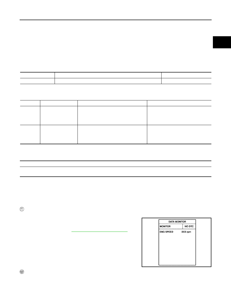
Select “DATA MONITOR””mode with CONSULT-II.

3.

Start engine and let it idle for 5 seconds.

4.

If DTC is detected, go to 

EC-566, "Diagnostic Procedure"

 .

 With GST

Follow the procedure “With CONSULT-II” above.

MONITOR ITEM

CONDITION

SPECIFICATION

THRTL RELAY

Ignition switch: ON

ON

DTC No.

Trouble diagnosis name

DTC detecting condition

Possible cause

P2100
2100

Throttle control motor 
relay circuit open

ECM detects a voltage of power source for 
throttle control motor is excessively low.

Harness or connectors
(Throttle control motor relay circuit is 
open)

Throttle control motor relay

P2103
2103

Throttle control motor 
relay circuit short

ECM detects the throttle control motor relay is 
stuck ON.

Harness or connectors
(Throttle control motor relay circuit is 
shorted)

Throttle control motor relay

Engine operating condition in fail-safe mode

ECM stops the electric throttle control actuator control, throttle valve is maintained at a fixed opening (approx. 5 degrees) by the return 
spring.

SEF058Y

EC-564

DTC P2100, P2103 THROTTLE CONTROL MOTOR RELAY

2006 Pathfinder

PROCEDURE FOR DTC P2103

TESTING CONDITION:
Before performing the following procedure, confirm that battery voltage is more than 8V.

 With CONSULT-II

1.

Turn ignition switch ON and wait at least 1 second.

2.

Select “DATA MONITOR” mode with CONSULT-II.

3.

If DTC is detected, go to 

EC-566, "Diagnostic Procedure"

 .

 With GST

Follow the procedure “With CONSULT-II” above.

SEF058Y

DTC P2100, P2103 THROTTLE CONTROL MOTOR RELAY

EC-565

C

D

E

F

G

H

I

J

K

L

M

A

EC

2006 Pathfinder

Wiring Diagram

UBS00KCG

BBWA1760E

EC-566

DTC P2100, P2103 THROTTLE CONTROL MOTOR RELAY

2006 Pathfinder

Specification data are reference values and are measured between each terminal and ground.
Pulse signal is measured by CONSULT-II.

CAUTION:

Do not use ECM ground terminals when measuring input/output voltage. Doing so may result in dam-
age to the ECM's transistor. Use a ground other than ECM terminals, such as the ground.

: Average voltage for pulse signal (Actual pulse signal can be confirmed by oscilloscope.)

Diagnostic Procedure

UBS00KCH

1. 

CHECK THROTTLE CONTROL MOTOR RELAY POWER SUPPLY CIRCUIT-I

1.

Turn ignition switch OFF.

2.

Check voltage between ECM terminal 104 and ground with
CONSULT-II or tester.

OK or NG

OK

>> GO TO 4.

NG

>> GO TO 2.

TER-

MINAL 

NO.

WIRE 

COLOR

ITEM

CONDITION

DATA (DC Voltage)

3

V

Throttle control motor relay 
power supply

[Ignition switch: ON]

BATTERY VOLTAGE
(11 - 14V)

4

L/W

Throttle control motor 
(Close)

[Ignition switch: ON]

Engine: Stopped

Shift lever: D

Accelerator pedal: Fully released

0 - 14V

5

L/B

Throttle control motor 
(Open)

[Ignition switch: ON]

Engine: Stopped

Shift lever: D

Accelerator pedal: Fully depressed

0 - 14V

104

O

Throttle control motor relay

[Ignition switch: OFF]

BATTERY VOLTAGE
(11 - 14V)

[Ignition switch: ON]

0 - 1.0V

PBIB1104E

PBIB1105E

Voltage: Battery voltage

PBIB1171E

DTC P2100, P2103 THROTTLE CONTROL MOTOR RELAY

EC-567

C

D

E

F

G

H

I

J

K

L

M

A

EC

2006 Pathfinder

2. 

CHECK THROTTLE CONTROL MOTOR RELAY POWER SUPPLY CIRCUIT-II

1.

Disconnect ECM harness connector.

2.

Disconnect IPDM E/R harness connector E122.

3.

Check continuity between ECM terminal 104 and IPDM E/R terminal 47.
Refer to Wiring Diagram.

4.

Also check harness for short to ground and short to power.

OK or NG

OK

>> GO TO 3.

NG

>> Repair open circuit or short to ground or short to power in harness or connectors.

3. 

CHECK FUSE

1.

Disconnect 20A fuse.

2.

Check 20A fuse for blown.

OK or NG

OK

>> GO TO 7.

NG

>> Replace 20A fuse.

4. 

CHECK THROTTLE CONTROL MOTOR RELAY INPUT SIGNAL CIRCUIT-I

1.

Check voltage between ECM terminal 3 and ground under the
following conditions with CONSULT-II or tester.

OK or NG

OK

>> GO TO 7.

NG

>> GO TO 5.

5. 

CHECK THROTTLE CONTROL MOTOR RELAY INPUT SIGNAL CIRCUIT-II

1.

Turn ignition switch OFF.

2.

Disconnect ECM harness connector.

3.

Disconnect IPDM E/R harness connector E119.

4.

Check continuity between ECM terminal 3 and IPDM E/R terminal 6.
Refer to Wiring Diagram.

5.

Also check harness for short to ground and short to power.

OK or NG

OK

>> GO TO 7.

NG

>> GO TO 6.

6. 

DETECT MALFUNCTIONING PART

Check the following.

Harness connectors E2, F32

Harness for open or short between ECM and IPDM E/R

>> Repair open circuit or short to ground or short to power in harness or connectors.

Continuity should exist.

Ignition switch

Voltage

OFF

Approximately 0V

ON

Battery voltage

(11 - 14V)

MBIB0028E

Continuity should exist.

EC-568

DTC P2100, P2103 THROTTLE CONTROL MOTOR RELAY

2006 Pathfinder

7. 

CHECK INTERMITTENT INCIDENT

Refer to 

EC-144, "TROUBLE DIAGNOSIS FOR INTERMITTENT INCIDENT"

 .

OK or NG

OK

>> Replace IPDM E/R. Refer to 

PG-18, "IPDM E/R (INTELLIGENT POWER DISTRIBUTION MOD-

ULE ENGINE ROOM)"

 .

NG

>> Repair or replace harness or connectors.

DTC P2101 ELECTRIC THROTTLE CONTROL FUNCTION

EC-569

C

D

E

F

G

H

I

J

K

L

M

A

EC

2006 Pathfinder

DTC P2101 ELECTRIC THROTTLE CONTROL FUNCTION

PFP:16119

Description

UBS00KC5

NOTE:
If DTC P2101 is displayed with DTC P2100 or P2119, first perform the trouble diagnosis for DTC P2100
or P2119. Refer to 

EC-563

 or 

EC-580

 .

Electric throttle control actuator consists of throttle control motor, throttle position sensor, etc.
The throttle control motor is operated by the ECM and it opens and closes the throttle valve.
The current opening angle of the throttle valve is detected by the throttle position sensor and it provides feed-
back to the ECM to control the throttle control motor to make the throttle valve opening angle properly in
response to driving condition.

On Board Diagnosis Logic

UBS00KC6

This self-diagnosis has the one trip detection logic.

FAIL-SAFE MODE

When the malfunction is detected, ECM enters fail-safe mode and the MIL lights up.

DTC Confirmation Procedure

UBS00KC7

NOTE:
If DTC Confirmation Procedure has been previously conducted, always turn ignition switch OFF and wait at
least 10 seconds before conducting the next test.
TESTING CONDITION:
Before performing the following procedure, confirm that battery voltage is more than 11V when the
engine is running.

 WITH CONSULT-II

1.

Turn ignition switch ON and wait at least 2 seconds.

2.

Select “DATA MONITOR” mode with CONSULT-II.

3.

Start engine and let it idle for 5 seconds.

4.

If DTC is detected, go to 

EC-571, "Diagnostic Procedure"

 .

 WITH GST

Follow the procedure “WITH CONSULT-II” above.

DTC No.

Trouble diagnosis name

DTC detecting condition

Possible cause

P2101
2101

Electric throttle control 
performance 

Electric throttle control function does not oper-
ate properly.

Harness or connectors
(Throttle control motor circuit is open or 
shorted)

Electric throttle control actuator

Engine operating condition in fail-safe mode

ECM stops the electric throttle control actuator control, throttle valve is maintained at a fixed opening (approx. 5 degrees) by the return 
spring.

SEF058Y

EC-570

DTC P2101 ELECTRIC THROTTLE CONTROL FUNCTION

2006 Pathfinder

Wiring Diagram

UBS00KC8

BBWA1759E


Content      ..     211      212      213      214     ..