Nissan Pathfinder (2006 year). Manual - part 210
DTC P1564 ASCD STEERING SWITCH
EC-539
C
D
E
F
G
H
I
J
K
L
M
A
EC
2006 Pathfinder
2.
CHECK ASCD STEERING SWITCH CIRCUIT
With CONSULT-II
1.
Turn ignition switch ON.
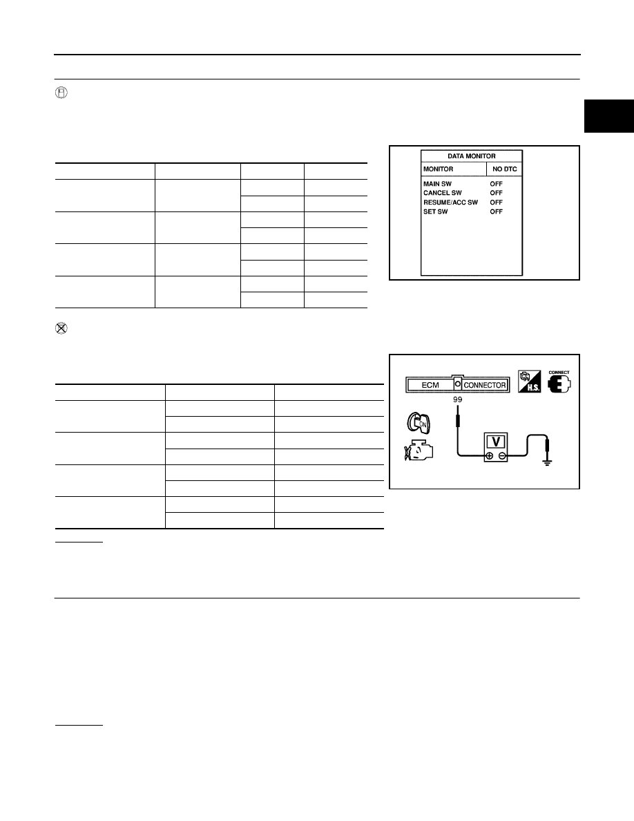
2.
Select “MAIN SW”, “CANCEL SW”, “RESUME/ACC SW” and “SET SW” in “DATA MONITOR” mode with
CONSULT-II.
3.
Check each item indication under the following conditions.
Without CONSULT-II
1.
Turn ignition switch ON.
2.
Check voltage between ECM terminal 99 and ground with press-
ing each button.
OK or NG
OK
>> GO TO 8.
NG
>> GO TO 3.
3.
CHECK ASCD STEERING SWITCH GROUND CIRCUIT FOR OPEN AND SHORT
1.
Turn ignition switch OFF.
2.
Disconnect combination switch harness connector.
3.
Disconnect ECM harness connector.
4.
Check harness continuity between combination switch terminal 17 and ECM terminal 67. Refer to Wiring
Diagram.
5.
Also check harness for short to ground and short to power.
OK or NG
OK
>> GO TO 5.
NG
>> GO TO 4.
Switch Monitor
item
Condition
Indication
MAIN switch
MAIN SW
Pressed
ON
Released
OFF
CANCEL switch
CANCEL SW
Pressed
ON
Released
OFF
RESUME/ACCELER-
ATE switch
RESUME/ACC SW
Pressed
ON
Released
OFF
SET/COAST switch
SET SW
Pressed
ON
Released
OFF
SEC006D
Switch
Condition
Voltage [V]
MAIN switch
Pressed
Approx. 0
Released
Approx. 4
CANCEL switch
Pressed
Approx. 1
Released
Approx. 4
RESUME/ACCELERATE
switch
Pressed
Approx. 3
Released
Approx. 4
SET/COAST switch
Pressed
Approx. 2
Released
Approx. 4
PBIB0311E
Continuity should exist.