Nissan Pathfinder (2006 year). Manual - part 166


  Index      Manuals     Nissan Pathfinder (2006 year) - Service and Repair Manual


Search            copyright infringement  


Content      ..     164      165      166      167     ..


Nissan Pathfinder (2006 year). Manual - part 166


DTC P0101 MAF SENSOR

EC-187

C

D

E

F

G

H

I

J

K

L

M

A

EC

2006 Pathfinder

DTC Confirmation Procedure

UBS00K5C

Perform PROCEDURE FOR MALFUNCTION A first.
If the DTC cannot be confirmed, perform PROCEDURE FOR MALFUNCTION B.

NOTE:
If DTC Confirmation Procedure has been previously conducted, always turn ignition switch OFF and wait at
least 10 seconds before conducting the next test.

PROCEDURE FOR MALFUNCTION A

NOTE:
If engine will not start or stops soon, wait at least 10 seconds with engine stopped (Ignition switch ON) instead
of running engine at idle speed.

 With CONSULT-II

1.

Turn ignition switch ON.

2.

Select “DATA MONITOR” mode with CONSULT-II.

3.

Start engine and warm it up to normal operating temperature.

4.

Run engine for at least 10 seconds at idle speed.

5.

If 1st trip DTC is detected, go to 

EC-190, "Diagnostic Procedure"

.

 With GST

Follow the procedure “With CONSULT-II” above.

PROCEDURE FOR MALFUNCTION B

CAUTION:

Always drive vehicle at a safe speed.

 With CONSULT-II 

1.

Turn ignition switch ON.

2.

Start engine and warm it up to normal operating temperature.
If engine cannot be started, go to 

EC-190, "Diagnostic Procedure"

 .

3.

Select “DATA MONITOR” mode with CONSULT-II.

4.

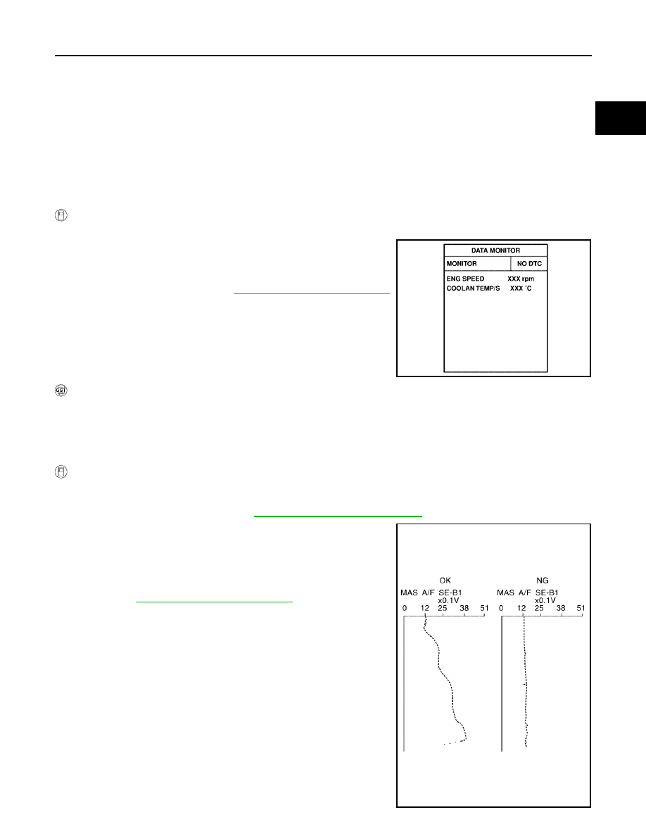
Check the voltage of “MAS A/F SE-B1” with “DATA MONITOR”.

5.

Increases engine speed to about 4,000 rpm.

6.

Monitor the linear voltage rise in response to engine speed
increases.
If NG, go to 

EC-190, "Diagnostic Procedure"

 .

If OK, go to following step.

SEF174Y

SEF243Y

EC-188

DTC P0101 MAF SENSOR

2006 Pathfinder

7.

Maintain the following conditions for at least 10 consecutive sec-
onds.

8.

If 1st trip DTC is detected, go to 

EC-190, "Diagnostic Procedure"

.

Overall Function Check

UBS00K5D

PROCEDURE FOR MALFUNCTION B

Use this procedure to check the overall function of the mass air flow sensor circuit. During this check, a 1st trip
DTC might not be confirmed.

 With GST

1.

Start engine and warm it up to normal operating temperature.

2.

Select Service $01 with GST.

3.

Check the mass air flow sensor signal with Service $01.

4.

Check for linear mass air flow sensor signal value rise in
response to increases to about 4,000 rpm in engine speed.

5.

If NG, go to 

EC-190, "Diagnostic Procedure"

 .

ENG SPEED

More than 2,000 rpm

THRTL SEN 1

More than 3V

THRTL SEN 2

More than 3V

Selector lever

Suitable position

Driving location

Driving vehicle uphill (Increased engine load) will help 
maintain the driving conditions required for this test.

PBIB0199E

SEF534P

DTC P0101 MAF SENSOR

EC-189

C

D

E

F

G

H

I

J

K

L

M

A

EC

2006 Pathfinder

Wiring Diagram

UBS00K5E

BBWA1922E

EC-190

DTC P0101 MAF SENSOR

2006 Pathfinder

Specification data are reference values and are measured between each terminal and ground.

CAUTION:

Do not use ECM ground terminals when measuring input/output voltage. Doing so may result in dam-
age to the ECM's transistor. Use a ground other than ECM terminals, such as the ground.

Diagnostic Procedure

UBS00K5F

1. 

INSPECTION START

Which malfunction (A or B) is duplicated?

A or B

A

>> GO TO 3.

B

>> GO TO 2.

2. 

CHECK INTAKE SYSTEM

Check the following for connection.

Air duct

Vacuum hoses

Intake air passage between air duct and intake manifold

OK or NG

OK

>> GO TO 3.

NG

>> Reconnect the parts.

TER-

MINAL 

NO.

WIRE 

COLOR

ITEM

CONDITION

DATA (DC Voltage)

51

P

Mass air flow sensor

[Engine is running]

Warm-up condition

Idle speed

0.9 - 1.2V

[Engine is running]

Warm-up condition

Engine speed: 2,500 rpm

1.5 - 1.8V

67

B

Sensor ground

[Engine is running]

Warm-up condition

Idle speed

Approximately 0V

111

BR

ECM relay
(Self shut-off)

[Engine is running]
[Ignition switch: OFF]

For a few seconds after turning ignition 
switch OFF

0 - 1.5V

[Ignition switch: OFF]

More than a few seconds after turning igni-
tion switch OFF

BATTERY VOLTAGE
(11 - 14V)

119

120

R
P

Power supply for ECM

[Ignition switch: ON]

BATTERY VOLTAGE
(11 - 14V)

DTC P0101 MAF SENSOR

EC-191

C

D

E

F

G

H

I

J

K

L

M

A

EC

2006 Pathfinder

3. 

CHECK GROUND CONNECTIONS

1.

Turn ignition switch OFF.

2.

Loosen and retighten three ground screws on the body. Refer to 

EC-151, "Ground Inspection"

 .

OK or NG

OK

>> GO TO 4.

NG

>> Repair or replace ground connections.

4. 

CHECK MAF SENSOR POWER SUPPLY CIRCUIT

1.

Disconnect mass air flow (MAF) sensor harness connector.

2.

Turn ignition switch ON.

3.

Check voltage between MAF sensor terminal 2 and ground with
CONSULT-II or tester.

OK or NG

OK

>> GO TO 6.

NG

>> GO TO 5.

5. 

DETECT MALFUNCTIONING PART

Check the following.

Harness connectors E2, F32

Harness for open or short between IPDM E/R and mass air flow sensor

Harness for open or short between mass air flow sensor and ECM

>> Repair harness or connectors.

BBIA0539E

BBIA0541E

Voltage: Battery voltage

PBIB1168E

EC-192

DTC P0101 MAF SENSOR

2006 Pathfinder

6. 

CHECK MAF SENSOR GROUND CIRCUIT FOR OPEN AND SHORT

1.

Turn ignition switch OFF.

2.

Disconnect ECM harness connector.

3.

Check harness continuity between MAF sensor terminal 3 and ECM terminal 67.
Refer to Wiring Diagram.

4.

Also check harness for short to ground and short to power.

OK or NG

OK

>> GO TO 7.

NG

>> Repair open circuit or short to ground or short to power in harness or connectors.

7. 

CHECK MAF SENSOR INPUT SIGNAL CIRCUIT FOR OPEN AND SHORT

1.

Check harness continuity between MAF sensor terminal 4 and ECM terminal 51.
Refer to Wiring Diagram.

2.

Also check harness for short to ground and short to power.

OK or NG

OK

>> GO TO 8.

NG

>> Repair open circuit or short to ground or short to power in harness or connectors.

8. 

CHECK INTAKE AIR TEMPERATURE SENSOR

Refer to 

EC-206, "Component Inspection"

 .

OK or NG

OK

>> GO TO 9.

NG

>> Replace intake air temperature sensor.

9. 

CHECK EVAP CONTROL SYSTEM PRESSURE SENSOR

Refer to 

EC-424, "Component Inspection"

 .

OK or NG

OK

>> GO TO 10.

NG

>> Replace EVAP control system pressure sensor.

10. 

CHECK MASS AIR FLOW SENSOR

Refer to 

EC-192, "Component Inspection"

 .

OK or NG

OK

>> GO TO 11.

NG

>> Replace mass air flow sensor.

11. 

CHECK INTERMITTENT INCIDENT

Refer to 

EC-144, "TROUBLE DIAGNOSIS FOR INTERMITTENT INCIDENT"

 .

>> INSPECTION END

Component Inspection

UBS00K5G

MASS AIR FLOW SENSOR

 With CONSULT-II

1.

Reconnect all harness connectors disconnected.

2.

Start engine and warm it up to normal operating temperature.

3.

Connect CONSULT-II and select “DATA MONITOR” mode.

Continuity should exist.

Continuity should exist.

DTC P0101 MAF SENSOR

EC-193

C

D

E

F

G

H

I

J

K

L

M

A

EC

2006 Pathfinder

4.

Select “MAS A/F SE-B1” and check indication under the follow-
ing conditions.

*: Check for linear voltage rise in response to engine being increased to about
4,000 rpm.

5.

If the voltage is out of specification, proceed the following.

a.

Check for the cause of uneven air flow through mass air flow sensor. Refer to following.

Crushed air ducts

Malfunctioning seal of air cleaner element

Uneven dirt of air cleaner element

Improper specification of intake air system parts

b.

If NG, repair or replace malfunctioning part and perform step 2 to 4 again.
If OK, go to next step.

6.

Turn ignition switch OFF.

7.

Disconnect mass air flow sensor harness connector and reconnect it again.

8.

Perform step 2 to 4 again.

9.

If NG, clean or replace mass air flow sensor.

 Without CONSULT-II

1.

Reconnect all harness connectors disconnected.

2.

Start engine and warm it up to normal operating temperature.

3.

Check voltage between ECM terminal 51 (Mass air flow sensor
signal) and ground.

*: Check for linear voltage rise in response to engine being increased to about
4,000 rpm.

4.

If the voltage is out of specification, proceed the following.

a.

Check for the cause of uneven air flow through mass air flow sensor. Refer to following.

Crushed air ducts

Malfunctioning seal of air cleaner element

Uneven dirt of air cleaner element

Improper specification of intake air system parts

b.

If NG, repair or replace malfunctioning part and perform step 2 to 3 again.
If OK, go to next step.

5.

Turn ignition switch OFF.

6.

Disconnect mass air flow sensor harness connector and reconnect it again.

7.

Perform step 2 and 3 again.

8.

If NG, clean or replace mass air flow sensor.

Condition

MAS A/F SE-B1 (V)

Ignition switch ON (Engine stopped.)

Approx. 0.4

Idle (Engine is warmed-up to normal 
operating temperature.)

0.9 - 1.2

2,500 rpm (Engine is warmed-up to 
normal operating temperature.)

1.5 - 1.8

Idle to about 4,000 rpm

0.9 - 1.2 to Approx. 2.4*

PBIB2371E

Condition

Voltage V

Ignition switch ON (Engine stopped.)

Approx. 0.4

Idle (Engine is warmed-up to normal 
operating temperature.)

0.9 - 1.2

2,500 rpm (Engine is warmed-up to 
normal operating temperature.)

1.5 - 1.8

Idle to about 4,000 rpm

0.9 - 1.2 to Approx. 2.4*

PBIB1106E

EC-194

DTC P0101 MAF SENSOR

2006 Pathfinder

Removal and Installation

UBS00K5H

MASS AIR FLOW SENSOR

Refer to 

EM-16, "AIR CLEANER AND AIR DUCT"

 .


Content      ..     164      165      166      167     ..