Nissan Pathfinder (2006 year). Manual - part 113
FRONT DISC BRAKE
BR-27
C
D
E
G
H
I
J
K
L
M
A
B
BR
2006 Pathfinder
4.
Using a suitable tool, remove piston seal from cylinder body.
CAUTION:
●
Be careful not to damage cylinder inner wall.
●
Do not reuse piston seal.
CALIPER INSPECTION
Cylinder Body
CAUTION:
●
Use new brake fluid for cleaning. Do not use mineral oils such as gasoline or kerosene. Refer to
MA-11, "RECOMMENDED FLUIDS AND LUBRICANTS"
.
●
Check inside surface of cylinder for score, rust, wear, damage or foreign materials. If any of the
above conditions are observed, replace cylinder body.
●
Minor damage from rust or foreign materials may be eliminated by polishing surface with a fine
emery paper. Replace cylinder body if necessary.
Torque Member
Check for wear, cracks, and damage. If damage or deformation is present, replace the affected part.
Piston
Check piston for score, rust, wear, damage or presence of foreign materials. Replace if any of the above con-
ditions are observed.
CAUTION:
Piston sliding surface is plated, do not polish with emery paper even if rust or foreign materials are
stuck to sliding surface.
Sliding Pins, and Sliding Pin Boots
Check sliding pin and sliding pin boot for wear, damage, and cracks. If damage or deformation is present,
replace the affected part.
CAUTION:
Trailing/upper sliding pin must be replaced at each service.
ASSEMBLY
CAUTION:
Do not use NISSAN Rubber Grease (KRE00 00010, KRE00 00010 01) when assembling.
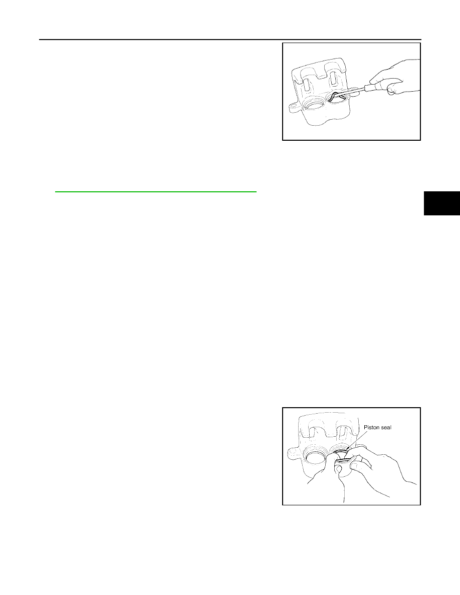
1.
Apply clean brake fluid to new piston seal and insert seal into
groove on cylinder body.
CAUTION:
Do not reuse piston seal.
SFIA0141E
SFIA2399E