Nissan Pathfinder (2006 year). Manual - part 112
BRAKE BOOSTER
BR-19
C
D
E
G
H
I
J
K
L
M
A
B
BR
2006 Pathfinder
Removal and Installation
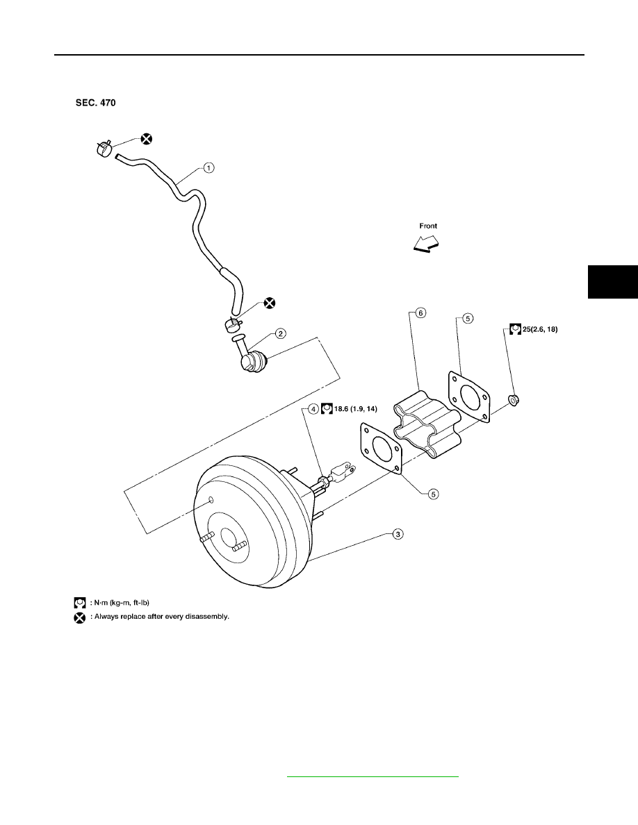
EFS0063R
Brake Booster
REMOVAL
CAUTION:
●
Be careful not to deform or bend brake piping while removing and installing brake booster.
●
Replace clevis pin if it is damaged.
●
Be careful not to damage brake booster stud bolt threads. If brake booster is tilted or inclined dur-
ing installation, dash panel may damage the threads.
●
Attach the check valve in the correct direction.
1.
Remove actuator and electric unit. Refer to
BRC-62, "Removal and Installation"
.
2.
Remove brake piping from brake master cylinder.
LFIA0241E
1.
Brake booster hose
2.
Brake booster vacuum check valve
3.
Brake booster
4.
Lock nut
5.
Gasket
6.
Spacer block