Nissan Pathfinder (2006 year). Manual - part 110


  Index      Manuals     Nissan Pathfinder (2006 year) - Service and Repair Manual


Search            copyright infringement  


Content      ..     108      109      110      111     ..


Nissan Pathfinder (2006 year). Manual - part 110


PRECAUTIONS

BR-3

C

D

E

G

H

I

J

K

L

M

A

B

BR

2006 Pathfinder

PRECAUTIONS

PFP:00001

Precautions for Supplemental Restraint System (SRS) “AIR BAG” and “SEAT 
BELT PRE-TENSIONER”

EFS00639

The Supplemental Restraint System such as “AIR BAG” and “SEAT BELT PRE-TENSIONER”, used along
with a front seat belt, helps to reduce the risk or severity of injury to the driver and front passenger for certain
types of collision. This system includes seat belt switch inputs and dual stage front air bag modules. The SRS
system uses the seat belt switches to determine the front air bag deployment, and may only deploy one front
air bag, depending on the severity of a collision and whether the front occupants are belted or unbelted.
Information necessary to service the system safely is included in the SRS and SB section of this Service Man-
ual.

WARNING:

To avoid rendering the SRS inoperative, which could increase the risk of personal injury or death
in the event of a collision which would result in air bag inflation, all maintenance must be per-
formed by an authorized NISSAN/INFINITI dealer.

Improper maintenance, including incorrect removal and installation of the SRS, can lead to per-
sonal injury caused by unintentional activation of the system. For removal of Spiral Cable and Air
Bag Module, see the SRS section.

Do not use electrical test equipment on any circuit related to the SRS unless instructed to in this
Service Manual. SRS wiring harnesses can be identified by yellow and/or orange harnesses or
harness connectors.

Precautions for Brake System

EFS0063A

Recommended fluid is Genuine NISSAN Super Heavy Duty Brake Fluid or equivalent. Refer to 

MA-11,

"Fluids and Lubricants"

 .

Do not reuse drained brake fluid.

Be careful not to splash brake fluid on painted areas.

To clean or wash all parts of master cylinder, disc brake caliper and wheel cylinder, use clean brake fluid.

Do not use mineral oils such as gasoline or kerosene. They will ruin rubber parts of the hydraulic system.

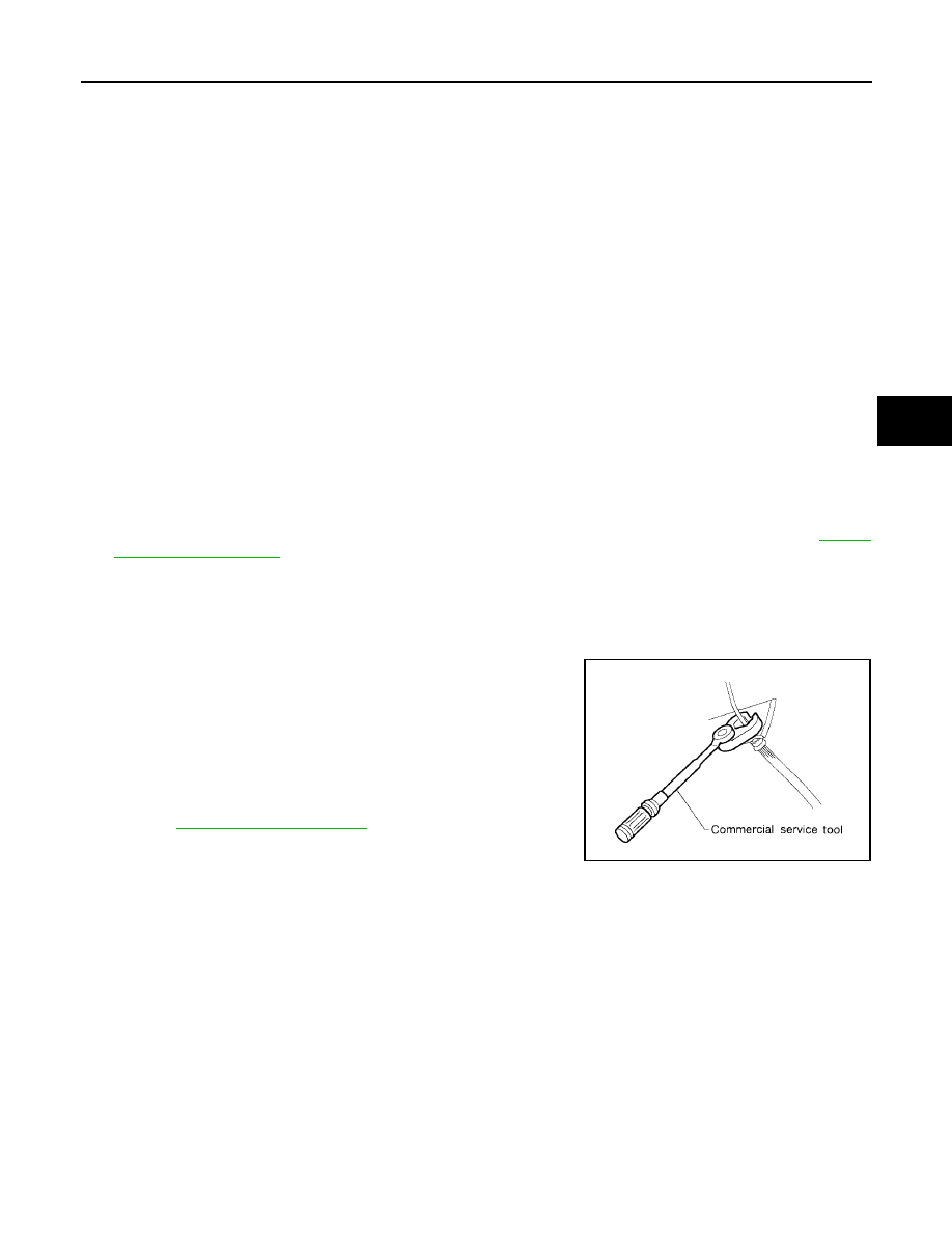
Use flare nut wrench when removing and installing brake tube.

Always check tightening torque when installing brake lines.

Before working, turn ignition switch to OFF and disconnect con-
nectors for ABS actuator and electric unit (control unit) or battery
terminals.

Burnish the brake contact surfaces after refinishing or replacing
drums or rotors, after replacing pads or linings, or if a soft pedal
occurs at very low mileage.
Refer to 

BR-29, "Brake Burnishing"

 .

WARNING:

Clean brake pads and shoes with a waste cloth, then wipe
with a dust collector.

SBR686C

BR-4

PREPARATION

2006 Pathfinder

PREPARATION

PFP:00002

Special Service Tool

EFS0063B

The actual shapes of Kent-Moore tools may differ from those of special service tools illustrated here.

Commercial Service Tools

EFS0063C

Tool number
(Kent-Moore No.)
Tool name

Description

(J-46532)
Brake and clutch pedal height measure-
ment tool

Measuring brake pedal height

LFIA0227E

Tool name

Description

1. Flare nut crowfoot
2. Torque wrench

Removing and installing each brake pip-
ing
a: 10 mm (0.39 in) / 12 mm (0.47 in)

Power tool

Removing nuts, bolts and screws

S-NT360

PBIC0190E

PBIC0191E

NOISE, VIBRATION, AND HARSHNESS (NVH) TROUBLESHOOTING

BR-5

C

D

E

G

H

I

J

K

L

M

A

B

BR

2006 Pathfinder

NOISE, VIBRATION, AND HARSHNESS (NVH) TROUBLESHOOTING

PFP:00003

NVH Troubleshooting Chart

EFS0063D

Use the chart below to help you find the cause of the symptom. If necessary, repair or replace these parts.

×

: Applicable

Reference page

BR-

2

3

BR-

3

0

BR-

2

3

BR-

3

0

BR-

2

4

BR-

3

1

BR-

2

8

BR-

3

4

BR-

2

8

BR-

3

4

BR-

2

8

BR-

3

4

BR-

2

8

BR-

3

4

BR-

2

8

BR-

3

4

BR-

2

9

BR-

3

5

BR-

2

9

BR-

3

5


PR

-3

, "

N

V

H

 T

rou

bl

e

s

hoo

ti

ng

 C

h

a

rt

"

FFD-

6

, "

N

V

H

 T

roub

le

s

hoo

ti

ng C

har

t"

 (

FFD)

RFD-

7

, "

N

V

H

 T

rou

bl

esho

ot

in

g

 C

h

a

rt

"


(RF

D

)

F

AX-

4, "

N

V

H

 T

roub

le

s

hoot

ing C

har

t"

 (

F

AX)

RAX-

4

, "

N

V

H

 T

ro

ubl

esh

oot

in

g C

h

ar

t"


(R

AX)

FSU-

4, "

N

V

H

 T

roub

le

shoo

ti

ng C

har

t"

 (F

S

U

),


RSU-

4

, "

N

V

H

 T

rou

bl

esho

ot

in

g

 C

h

a

rt

"


(RS

U

)

WT

-4

, "

N

V

H

 T

rou

bl

e

s

hoo

ti

ng C

har

t"

PS

-5

, "

N

V

H

 T

rou

bl

esho

ot

in

g

 C

h

a

rt

"

Possible cause and
SUSPECTED PARTS

Pads -

 da

m

a

ged

Pads 

- un

even

 w

e

a

r

Shi

m

s

 d

a

m

aged

R

o

to

r im

b

a

la

n

c

e

R

o

to

r dam

ag

e

R

o

to

r r

u

nout

R

o

to

r def

or

m

a

ti

on

Ro

to

r d

e

fle

c

ti

o

n

R

o

to

r ru

st

R

o

to

r t

h

ic

knes

s var

iat

io

n

PROPELLER SHAFT

DI

FFERE

N

T

IA

L

DR

IVESHAFT


SUSPENSI

ON

TI

RES AND ROAD 

W

H

EEL

STEERIN

G

Symptom

Noise

×

×

×

×

×

×

×

×

×

Shake

×

×

×

×

×

×

Shimmy, Shudder

×

×

×

×

×

×

×

×

×

×

×

BR-6

BRAKE PEDAL

2006 Pathfinder

BRAKE PEDAL

PFP:46501

Inspection and Adjustment 

EFS0063E

INSPECTION

1.

Inspect the brake pedal free height "H" from dash lower panel
using Tool. 

2.

Adjust the height referring to the following specifications.

CAUTION:

The adjustable pedal must be in the frontmost (closest to
the floor) position for pedal height measurement.

Unit: mm (in)

ADJUSTMENT

1.

Loosen the stop lamp switch and ASCD cancel switch by turning 45

°

 counterclockwise.

2.

Loosen lock nut on the input rod, then turn input rod to adjust the
pedal to specified height. When finished adjusting, tighten lock
nut.

CAUTION:

Make sure that the screw portion of the end of input rod is
located inside the clevis.

3.

With the pedal pulled up and held by hand, press the stop lamp
switch and the ASCD cancel switch in until threaded ends con-
tact pedal arm. 

4.

With the threaded ends of the stop lamp switch and ASCD can-
cel switch contacting the pedal arm, turn the switches 45

°

 clockwise to lock in place.

CAUTION:

Make sure that the gap "C

1

  or C

2

 " between the rubber stops and switch ends are within specifica-

tion.

5.

Check the pedal play.

Tool

:

(J-46532)

WFIA0160E

Free height "H"

: 182.1 - 192.1 (7.17 - 7.56)

Depressed pedal height ("D" [under a force of 490 N (50 kg, 110 
lb) with engine running]

: 105 - 115 (4.13 - 4.53)

Clearance between pedal stopper and threaded end of stop lamp 
switch and ASCD cancel switch "C

1

 " or "C

2

 "

: 0.74 - 1.96 (0.029 - 0.077)

Pedal play "A"

: 3 - 11 (0.12 - 0.43)

Lock nut

: 18.6 N·m (1.9 kg-m, 14 ft-lb)

SBR229E

BRAKE PEDAL

BR-7

C

D

E

G

H

I

J

K

L

M

A

B

BR

2006 Pathfinder

CAUTION:

Make sure that the stop lamp goes off when the pedal is released.

6.

Start the engine and check the height of the brake pedal when depressing it.

Removal and Installation 

EFS0063F

COMPONENTS

Adjustable Brake Pedal

LFIA0231E

1.

Brake pedal assembly

2.

Snap pin

3.

Clip

4.

Stop lamp switch

5.

Pedal pad

6.

Clevis pin

7.

ASCD cancel switch

BR-8

BRAKE PEDAL

2006 Pathfinder

Non-adjustable Brake Pedal

REMOVAL FOR ADJUSTABLE BRAKE PEDAL

WARNING:

Do not deform the brake tube. 

CAUTION:

Before removal and installation the accelerator and brake pedals must be in the forward most
position (closest to the floor). This is to align the base position of the accelerator and brake ped-
als.

Do not disassemble the brake pedal adjusting mechanism.

Avoid damage from dropping the brake pedal assembly during handling.

Keep the brake pedal assembly away from water.

1.

Remove the lower driver instrument panel. Refer to 

IP-10, "Removal and Installation"

 .

2.

Remove the stop lamp switch and ASCD cancel switch from the pedal assembly.

LFIA0232E

1.

Brake pedal assembly

2.

Snap pin

3.

Clip

4.

Stop lamp switch

5.

Pedal pad

6.

Clevis pin

7.

ASCD cancel switch

BRAKE PEDAL

BR-9

C

D

E

G

H

I

J

K

L

M

A

B

BR

2006 Pathfinder

3.

Disconnect the adjustable brake pedal cable from the adjustable
pedal.

Release the two lock tabs, then pull the adjustable brake
pedal cable to disconnect it from the adjustable brake pedal.

4.

Remove snap pin and clevis pin from the clevis of the brake booster.

5.

Remove mounting nuts and the pedal assembly.

Temporarily install the nuts by hand to support the booster.

CAUTION:

Before removal and installation the accelerator and brake pedals must be in the frontmost posi-
tion (closest to the floor). This is to align the base position of the accelerator and brake pedals.

Do not disassemble the brake pedal adjusting mechanism.

Avoid damage from dropping the brake pedal assembly during handling.

Keep the brake pedal assembly away from water.

REMOVAL FOR NON-ADJUSTABLE BRAKE PEDAL

WARNING:

Do not deform the brake tube. 

CAUTION:

Do not disassemble the brake pedal assembly.

Avoid damage from dropping the brake pedal assembly during handling.

Keep the brake pedal assembly away from water.

1.

Remove the lower driver instrument panel. Refer to 

IP-10, "Removal and Installation"

 .

2.

Remove the stop lamp switch and ASCD cancel switch from the pedal assembly.

3.

Remove snap pin and clevis pin from the clevis of the brake booster.

4.

Remove mounting nuts and the pedal assembly.

Temporarily install the nuts by hand to support the booster.

INSPECTION AFTER REMOVAL

Check brake pedal for following items.

Crack or deformation of clevis pin stopper

Clevis pin deformation

Crack of any welded portion

Brake pedal bend

INSTALLATION

1.

Installation is in the reverse order of removal.

Check the brake pedal for smooth operation. There should be no binding or sticking when applying or
releasing the brake pedal.

On models equipped with adjustable brake pedal, check the adjustable feature for smooth operation.
There should be no binding or sticking when adjusting the brake pedal forward and backward.

LFIA0233E

SBR997

BR-10

BRAKE PEDAL

2006 Pathfinder

After installing the brake pedal assembly in the vehicle, be sure to adjust it. Refer to 

BR-6, "Inspection

and Adjustment"

 .


Content      ..     108      109      110      111     ..