Nissan Pathfinder (2006 year). Manual - part 98


  Index      Manuals     Nissan Pathfinder (2006 year) - Service and Repair Manual


Search            copyright infringement  


Content      ..     96      97      98      99     ..


Nissan Pathfinder (2006 year). Manual - part 98


VEHICLE SECURITY (THEFT WARNING) SYSTEM

BL-85

C

D

E

F

G

H

J

K

L

M

A

B

BL

2006 Pathfinder

2. 

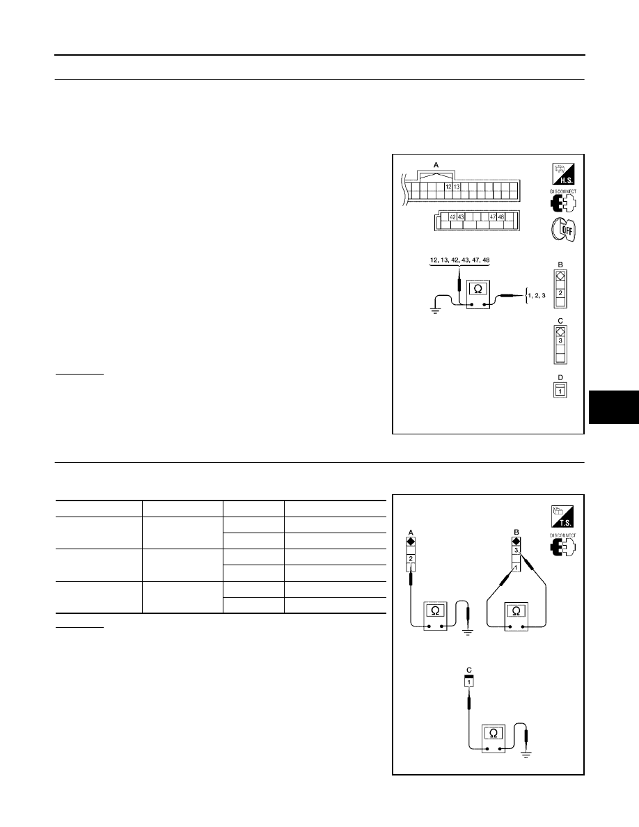
CHECK DOOR AND GLASS HATCH AJAR SWITCH CIRCUIT

1.

Turn ignition switch OFF.

2.

Disconnect door switch, glass hatch ajar switch and BCM.

3.

Check continuity between door switch connector (B) B8 (Front LH), B108 (Front RH), B18 (Rear LH),
B116 (Rear RH) terminal 2 or back door switch connector (C) D502 terminal 3 or glass hatch ajar switch
connector (D) D503 terminal 1 and BCM connector (A) M18, M19 terminals 12, 13, 42, 43, 47 and 48.

4.

Check continuity between door switch connector (B) B8 (Front
LH),   B108 (Front RH), B18 (Rear LH), B116 (Rear RH) terminal
2 or back door switch connector (C) D502 terminal 3 or glass
hatch ajar switch connector (D) D503 terminal 1 and ground.

OK or NG

OK

>> GO TO 3.

NG

>> Repair or replace harness.

3. 

CHECK DOOR AND GLASS HATCH AJAR SWITCHES

Check continuity between front/rear door switch connector (A) terminal 2 or back door switch connector (B)
terminal 3 or glass hatch ajar switch connector (C) terminal 1 and ground.

OK or NG

OK

>> Check switch case ground condition (front and rear door

and glass hatch) or ground circuit (back door).

NG

>> Replace door or glass hatch ajar switch.

1 - 42

: Continuity should exist.

2 - 47

: Continuity should exist.

2 - 12

: Continuity should exist.

2 - 48

: Continuity should exist.

2 - 13

: Continuity should exist.

3 - 43

: Continuity should exist.

1 - Ground

: Continuity should not exist.

2 - Ground

: Continuity should not exist.

3 - Ground

: Continuity should not exist.

WIIA0738E

Switch

Terminals

Condition

Continuity

A: Door switch 

(front and rear)

2 – Ground

Open

Yes

Closed

No

B: Back door switch

1 – 3

Open

Yes

Closed

No

C: Glass hatch ajar 

switch

1 – Ground

Open

Yes

Closed

No

WIIA0739E

BL-86

VEHICLE SECURITY (THEFT WARNING) SYSTEM

2006 Pathfinder

Diagnostic Procedure 2

EIS007PW

SECURITY INDICATOR LAMP CHECK

1. 

SECURITY INDICATOR LAMP ACTIVE TEST

With CONSULT-II

Check "THEFT IND” in "ACTIVE TEST" mode with CONSULT-II.

Without CONSULT-II

1.

Turn ignition switch OFF.

2.

Check voltage between BCM harness connector M18 terminal
23 and ground.

OK or NG

OK

>> Security indicator lamp is OK.

NG

>> GO TO 2.

2. 

SECURITY INDICATOR LAMP CHECK

Check security indicator lamp condition. Refer to 

DI-11, "SELF-DIAGNOSIS FUNCTION"

 .

OK or NG

OK

>> GO TO 3.

NG

>> Replace combination meter. Refer to 

IP-14, "COMBINATION METER"

 .

LIIA0044E

Connector

Terminal

Security indi-

cator lamp 

condition

Voltage (V)

(Approx.)

(+)

(-)

M18

23

Ground

Illuminated

0

Not illumi-

nated

Battery volt-

age

PIIA6230E

VEHICLE SECURITY (THEFT WARNING) SYSTEM

BL-87

C

D

E

F

G

H

J

K

L

M

A

B

BL

2006 Pathfinder

3. 

CHECK HARNESS CONTINUITY

1.

Turn ignition switch OFF.

2.

Disconnect BCM and combination meter connector.

3.

Check continuity between BCM connector M18 terminal 23 and
combination meter harness connector M24 terminal 39.

4.

Check continuity between BCM connector M18 terminal 23 and
ground.

OK or NG

OK

>> Check the following:

10A fuse [No. 19, located in fuse block (J/B)]

Harness for open or short between combination meter and fuse

NG

>> Repair or replace harness.

Diagnostic Procedure 3

EIS007PX

1. 

CHECK DOOR KEY CYLINDER SWITCH LH

With CONSULT-II

Check front door lock assembly LH (key cylinder switch) ("KEY CYL LK-SW") and ("KEY CYL UN-SW") in
DATA MONITOR mode with CONSULT-II. Refer to 

BL-27, "DATA MONITOR"

 .

When key inserted in left front key cylinder is turned to LOCK:

When key inserted in left front key cylinder is turned to
UNLOCK:

Without CONSULT-II

Check voltage between BCM connector M18 terminals 7, 8 and
ground.

OK or NG

OK

>> Key cylinder switch signal is OK.

NG

>> GO TO 2.

23 - 39

: Continuity should exist.

23 - Ground

: Continuity should not exist.

WIIA0461E

KEY CYL LK-SW

: ON

KEY CYL UN-SW

: ON

LIIA0188E

Connector

Terminals

Condition of left front key 

cylinder

Voltage (V)

(Approx.)

(+)

(–)

M18

7

Ground

Neutral/Lock

5

Unlock

0

8

Neutral/Unlock

5

Lock

0

WIIA0457E

BL-88

VEHICLE SECURITY (THEFT WARNING) SYSTEM

2006 Pathfinder

2. 

CHECK FRONT DOOR LOCK ASSEMBLY LH (KEY CYLINDER SWITCH)

1.

Turn ignition switch OFF.

2.

Disconnect front door lock assembly LH (key cylinder switch).

3.

Check continuity between front door lock assembly LH (key cyl-
inder switch) connector terminals 3, 4 and 5.

OK or NG

OK

>> GO TO 3.

NG

>> Replace front door lock assembly LH (key cylinder switch). Refer to 

BL-95, "Removal and Installa-

tion"

  .

3. 

CHECK FRONT DOOR LOCK ASSEMBLY LH HARNESS

1.

Disconnect BCM.

2.

Check continuity between BCM connector M18 terminals 7, 8
and front door lock assembly LH connector D14 terminals 3, 5.

3.

Check continuity between BCM connector M18 terminals 7, 8
and ground.

OK or NG

OK

>> GO TO 4.

NG

>> Repair or replace harness

4. 

CHECK FRONT DOOR LOCK ASSEMBLY LH GROUND

Check continuity between front door lock assembly LH connector
D14 terminal 4 and ground.

OK or NG

OK

>> Replace BCM. Refer to 

BCS-27, "Removal and Installa-

tion"

  .

NG

>> Repair or replace harness

Terminals

Condition

Continuity

4 – 5

Key is turned to LOCK.

Yes

Key is in N position or turned to 

UNLOCK

No

3 – 4

Key is turned to UNLOCK.

Yes

Key is in N position or turned to LOCK

No

WIIA0458E

7 - 3

: Continuity should exist.

8 - 5

: Continuity should exist.

7 - Ground

: Continuity should not exist.

8 - Ground

: Continuity should not exist.

WIIA0676E

4 - Ground

: Continuity should exist.

WIIA0677E

VEHICLE SECURITY (THEFT WARNING) SYSTEM

BL-89

C

D

E

F

G

H

J

K

L

M

A

B

BL

2006 Pathfinder

Diagnostic Procedure 4

EIS007PY

VEHICLE SECURITY HORN ALARM CHECK

1. 

CHECK HORN OPERATION

Check if horn sounds with horn switch.

Does horn operate?

Yes

>> Check harness for open or short between IPDM E/R and horn relay.

No

>> Check horn circuit. Refer to 

WW-48, "HORN"

 .

Diagnostic Procedure 5

EIS007PZ

VEHICLE SECURITY HEADLAMP ALARM CHECK 

1. 

CHECK VEHICLE SECURITY HEADLAMP ALARM OPERATION

Check if headlamps operate with lighting switch.

Do headlamps come on when turning switch ON?

Yes

>> Headlamp alarm is OK.

No

>> Check headlamp system. Refer to 

LT-5, "HEADLAMP (FOR USA)"

 .

Diagnostic Procedure 6

EIS007Q0

DOOR LOCK/UNLOCK SWITCH CHECK 

1. 

CHECK DOOR LOCK/UNLOCK SWITCH INPUT SIGNAL

Check if power door lock operates with door lock/unlock switch.

Do doors lock/unlock when using each door lock/unlock switch?

Yes

>> Door lock/unlock switch is OK.

No

>> Refer to 

BL-32, "Door Lock/Unlock Switch Check"

 .

BL-90

DOOR

2006 Pathfinder

DOOR

PFP:80100

Fitting Adjustment

EIS007Q1

FRONT DOOR
Longitudinal clearance and surface height adjustment at front end

1.

Remove the fender. Refer to 

EI-18, "FRONT FENDER"

 .

2.

Loosen the hinge bolts. Raise or lower the front door at rear end to adjust.

3.

Install the fender. Refer to 

EI-18, "FRONT FENDER"

 .

REAR DOOR
Longitudinal clearance and surface height adjustment at front end

1.

Remove the center pillar upper finisher. Refer to 

EI-27, "BODY SIDE TRIM"

 .

2.

Loosen the lower hinge bolts.

3.

From inside the vehicle, loosen the upper hinge nuts. Open the door, and raise or lower the rear end of the
door to adjust.

4.

Install the center pillar lower finisher. Refer to 

EI-27, "BODY SIDE TRIM"

 .

A.

4.5 

±

 1.0 mm (0.177 

±

 0.039 in)

WIIA0732E

DOOR

BL-91

C

D

E

F

G

H

J

K

L

M

A

B

BL

2006 Pathfinder

BACK DOOR
Longitudinal clearance and surface height adjustment 

1.

Open and support the back door.

2.

Slightly loosen the hinge nuts.

3.

Reposition the door as necessary and tighten the nuts.

4.

Confirm the adjustment. Repeat as necessary to obtain the desired fit.

1.

Back door assembly

2.

Back door hinge

3.

Tail lamp assembly

4.

Rear bumper fascia

5.

Roof

6.

Side window glass

a.

7.2 

±

 2.0 mm (0.28 

±

 0.06 in)

b.

6.0 

±

 1.5 mm (0.24 

±

 0.06 in)

c.

2.0 

±

  2.0 mm ( 0.08 

±

 0.08 in)

d.

1.0 

±

 1.5 mm (0.04 

±

 0.06 in)

e.

8.0 

±

 1.5 mm (0.31 

±

 0.06 in)

f.

5.3 

±

  2.0 mm (0.21 

±

 0.08 in)

g.

0.8 

±

 2.0 mm (0.03 

±

 0.08 in)

h.

0.8 

±

 1.0 mm (0.03 

±

 0.04 in)

j.

2.0 

±

 1.0 mm (0.08 

±

  0.04 in)

WIIA0733E

BL-92

DOOR

2006 Pathfinder

STRIKER ADJUSTMENT
BODY SIDE DOORS

1.

Adjust the striker so that it becomes parallel with the lock inser-
tion direction.

BACK DOOR

1.

Adjust the striker so that it becomes parallel with the lock inser-
tion direction.

Removal and Installation

EIS007Q2

FRONT DOOR

CAUTION:

When removing and installing the door assembly, support the door with a jack and shop cloth to
protect the door and body.

When removing and installing door assembly, be sure to carry out the fitting adjustment.

Check the hinge rotating part for poor lubrication. If necessary, apply "body grease".

1.

Remove the front door glass and regulator. Refer to 

GW-57, "FRONT DOOR GLASS AND REGULATOR"

.

2.

Remove the door harness.

3.

Remove the check link bolt from the hinge pillar.

4.

Remove the door-side hinge nuts, and the door assembly.

WIIA0734E

WIIA0735E

Check link to hinge pillar 
bolt

14.7 N·m (1.5 kg-m, 11 ft-lb)

LIIA1726E


Content      ..     96      97      98      99     ..