Nissan Pathfinder (2006 year). Manual - part 95


  Index      Manuals     Nissan Pathfinder (2006 year) - Service and Repair Manual


Search            copyright infringement  


Content      ..     93      94      95      96     ..


Nissan Pathfinder (2006 year). Manual - part 95


REMOTE KEYLESS ENTRY SYSTEM

BL-61

C

D

E

F

G

H

J

K

L

M

A

B

BL

2006 Pathfinder

4. 

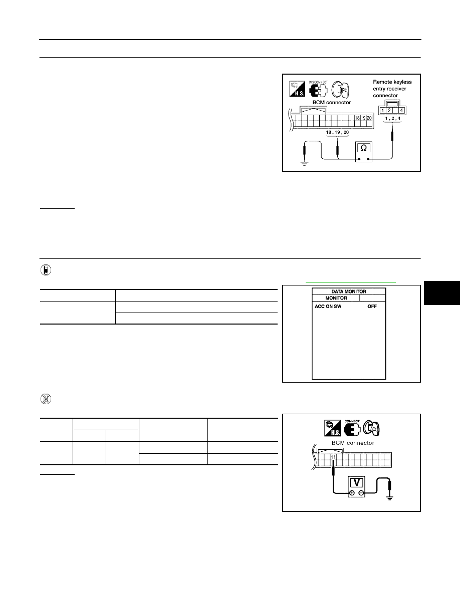
HARNESS INSPECTION BETWEEN BCM AND REMOTE KEYLESS ENTRY RECEIVER

1.

Disconnect remote keyless entry receiver and BCM connectors.

2.

Check continuity between remote keyless entry receiver con-
nector M120 terminals 1, 2, 4 and BCM connector M18 termi-
nals 18, 19, 20.

3.

Check continuity between remote keyless entry receiver termi-
nals 1, 2 and 4 and ground.

OK or NG

OK

>> Replace remote keyless entry receiver.

NG

>> Repair or replace the harness between the remote keyless entry receiver and BCM.

ACC Power Check

EIS007PC

1. 

CHECK ACC POWER

With CONSULT-II

Check "ACC ON SW" in DATA MONITOR mode with CONSULT–II. Refer to 

BL-27, "DATA MONITOR"

 .

Without CONSULT-II

Check voltage between BCM connector M18 terminal 11 and ground.

OK or NG

OK

>> ACC power circuit is OK.

NG

>> Check the following:

10A fuse [No. 4, located in fuse block (J/B)]

Harness for open or short.

1 - 18

: Continuity should exist

2 - 20

: Continuity should exist

4 - 19

: Continuity should exist

1 - Ground

: Continuity should not exist

2 - Ground

: Continuity should not exist

4 - Ground

: Continuity should not exist

WIIA0308E

Monitor Item

Condition

ACC ON SW

Ignition switch position is ACC       : ON

Ignition switch position is OFF       : OFF

PIIA3367E

Connec-

tor

Terminal

Condition

Voltage (V) 

(Approx.)

(+)

(–)

M18

11

Ground

ACC

Battery voltage

OFF

0

PIIA7002E

BL-62

REMOTE KEYLESS ENTRY SYSTEM

2006 Pathfinder

IPDM E/R Operation Check

EIS007PD

1. 

CHECK IPDM E/R INPUT VOLTAGE

Check voltage between IPDM E/R connector E122 terminal 45 and ground.

OK or NG

OK

>> Replace IPDM E/R. Refer to 

PG-32, "Removal and

Installation of IPDM E/R"

 .

NG

>> GO TO 2.

2. 

CHECK IPDM E/R INPUT VOLTAGE CIRCUIT

1.

Turn ignition switch OFF.

2.

Disconnect IPDM E/R and horn relay.

3.

Check continuity between IPDM E/R connector E122 terminal 45 and horn relay connector H-1 terminal 1.

4.

Check continuity between IPDM E/R connector E122 terminal 45 and ground.

OK or NG

OK

>> Further inspection is necessary. Refer to 

BL-54, "SYMP-

TOM CHART"

 .

NG

>> Repair or replace harness.

Check Hazard Function

EIS007PE

1. 

CHECK HAZARD WARNING LAMP

Does hazard indicator flash with hazard switch?

Yes or No

Yes

>> Hazard warning lamp circuit is OK.

No

>> Check hazard indicator. Refer to

LT-64, "TURN SIGNAL AND HAZARD WARNING LAMPS"

 .

Check Horn Function

EIS007PF

First, perform the "SELF-DIAG RESULTS" in "BCM" with CONSULT-II, then perform the trouble diagnosis of
malfunction system indicated in "SELF-DIAG RESULTS" of "BCM".

1. 

CHECK HORN FUNCTION

Does horn sound with horn switch?

Yes or No

Yes

>> Horn circuit is OK.

No

>> Check horn circuit. Refer to 

WW-48, "HORN"

 .

Check Headlamp Function

EIS007PG

First, perform the "SELF-DIAG RESULTS" in "BCM" with CONSULT-II, then perform the trouble diagnosis of
malfunction system indicated in "SELF-DIAG RESULTS" of "BCM".

Connector

Terminal

Voltage (V) 

(Approx.)

(+)

(–)

E122

45

Ground

Battery voltage

LIIA1053E

45 - 1

: Continuity should exist.

45 - Ground

: Continuity should not exist.

WIIA0679E

REMOTE KEYLESS ENTRY SYSTEM

BL-63

C

D

E

F

G

H

J

K

L

M

A

B

BL

2006 Pathfinder

1. 

CHECK HEADLAMP OPERATION

Does headlamp come on when turning lighting switch ON?

Yes or No

Yes

>> Headlamp operation circuit is OK.

No

>> Check headlamp circuit. Refer to 

LT-5, "HEADLAMP (FOR USA)"

 .

Check Room Lamp Illumination Function

EIS007PH

1. 

CHECK ROOM LAMP ILLUMINATION FUNCTION

When room lamp switch is in DOOR position, open the front door LH or RH.

OK or NG

OK

>> System is OK.

NG

>> Check room lamp illumination circuit. Refer to 

LT-115, "INTERIOR ROOM LAMP"

 .

Room lamp and ignition keyhole illumination should illuminate.

BL-64

REMOTE KEYLESS ENTRY SYSTEM

2006 Pathfinder

ID Code Entry Procedure

EIS007PI

KEYFOB ID SET UP WITH CONSULT-II

NOTE:

If a keyfob is lost, the ID code of the lost keyfob must be erased to prevent unauthorized use. A
specific ID code can be erased with CONSULT-II. However, when the ID code of a lost keyfob is not
known, all controller ID codes should be erased. After all ID codes are erased, the ID codes of all
remaining and/or new keyfobs must be re-registered.

When registering an additional keyfob, the existing ID codes in memory may or may not be erased.
If five ID codes are stored in memory when an additional code is registered, only the oldest code is
erased. If less than five codes are stored in memory when an additional code is registered, the
new ID code is added and no ID codes are erased.

Entry of a maximum of five ID codes is allowed. When more than five codes are entered, the oldest
ID code will be erased.

Even if the same ID code that is already in memory is input, the same ID code can be entered. The
code is counted as an additional code.

CAUTION:

If CONSULT-II is used with no connection of CONSULT-II CONVERTER, malfunctions might be
detected in self-diagnosis depending on control unit which carries on CAN communication.
1.

Turn ignition switch OFF.

2.

Connect CONSULT-II and CONSULT-II CONVERTER to the
data link connector.

3.

Turn ignition switch ON.

4.

Touch “START (NISSAN BASED VHCL)”.

5.

Touch “BCM”.
If "BCM" is not indicated, refer to 

GI-40, "CONSULT-II Data Link

Connector (DLC) Circuit"

 .

BBIA0538E

BCIA0029E

BCIA0030E

REMOTE KEYLESS ENTRY SYSTEM

BL-65

C

D

E

F

G

H

J

K

L

M

A

B

BL

2006 Pathfinder

6.

Touch “MULTI REMOTE ENT”.

7.

Touch “WORK SUPPORT”.

8.

The items are shown on the figure can be set up.

“REMO CONT ID REGIST”
Use this mode to register a keyfob ID code.

NOTE:
Register the ID code when keyfob or BCM is replaced, or
when additional keyfob is required.

“REMO CONT ID ERASUR”
Use this mode to erase a keyfob ID code.

“REMO CONT ID CONFIR”
Use this mode to confirm if a keyfob ID code is registered or
not.

LIIA0194E

BCIA0031E

LIIA1147E

BL-66

REMOTE KEYLESS ENTRY SYSTEM

2006 Pathfinder

KEYFOB ID SET UP WITHOUT CONSULT-II

LIIA1670E

REMOTE KEYLESS ENTRY SYSTEM

BL-67

C

D

E

F

G

H

J

K

L

M

A

B

BL

2006 Pathfinder

NOTE:

If a keyfob is lost, the ID code of the lost keyfob must be erased to prevent unauthorized use. A specific ID
code can be erased with CONSULT-II. However, when the ID code of a lost keyfob is not known, all con-
troller ID codes should be erased. After all ID codes are erased, the ID codes of all remaining and/or new
keyfobs must be re-registered.
To erase all ID codes in memory, register one ID code (keyfob) five times. After all ID codes are erased,
the ID codes of all remaining and/or new keyfobs must be re-registered.

When registering an additional keyfob, the existing ID codes in memory may or may not be erased. If five
ID codes are stored in memory, when an additional code is registered, only the oldest code is erased. If
less than five ID codes are stored in memory, when an additional ID code is registered, the new ID code is
added and no ID codes are erased.

If you need to activate more than two additional new keyfobs, repeat the procedure “Additional ID code
entry” for each new keyfob.

Entry of maximum five ID codes is allowed. When more than five ID codes are entered, the oldest ID code
will be erased.

Even if same ID code that is already in the memory is input, the same ID code can be entered. The code
is counted as an additional code.

Keyfob Battery Replacement

EIS007PJ

LIIA1514E

BL-68

VEHICLE SECURITY (THEFT WARNING) SYSTEM

2006 Pathfinder

VEHICLE SECURITY (THEFT WARNING) SYSTEM

PFP:28491

Component Parts and Harness Connector Location

EIS007PK

LIIA2413E

1.

IPDM E/R E118, E119, E120, E121, 
E122, E123, E124

2.

BCM M18, M19, M20
(view with instrument lower panel LH 
removed)

3.

Key switch M27

4.

Horns E3, E162
(Behind front combination lamp LH)

5.

Front door lock assembly LH (key cylin-
der switch) D14

6.

Main power window and door lock/
unlock switch D7
Power window and door lock/unlock 
switch RH D105

7.

Front door switch
LH B8
RH B108

8.

Rear door switch
LH B18
RH B116

9.

Back door switch D502
Back door lock actuator D508

10. Combination meter M24

11.

Glass hatch ajar switch D503


Content      ..     93      94      95      96     ..