Nissan Pathfinder (2006 year). Manual - part 78
NAVIGATION SYSTEM
AV-115
C
D
E
F
G
H
I
J
L
M
A
B
AV
2006 Pathfinder
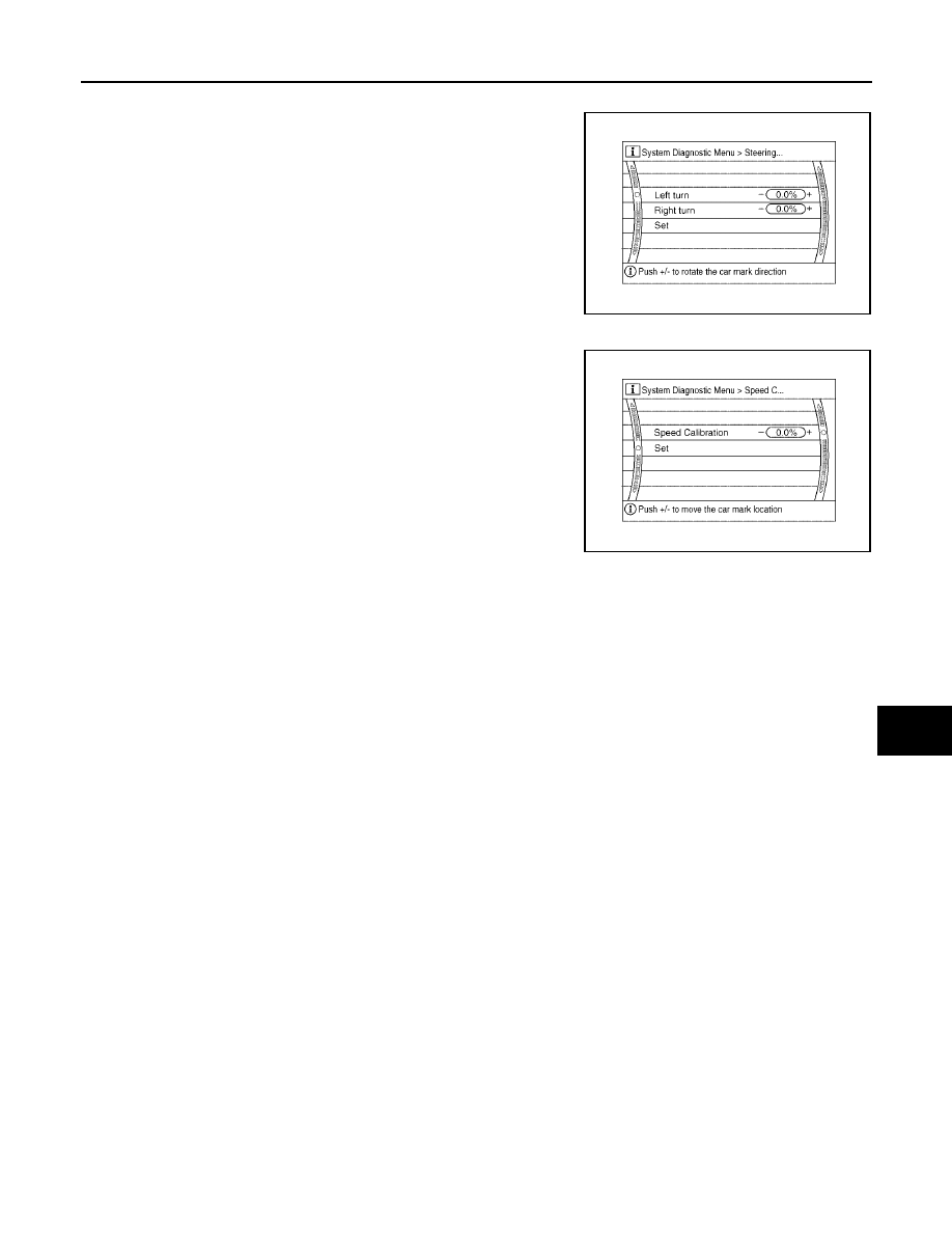
Angle adjustment
●
Adjusts turning angle output detected by the gyroscope.
Speed Calibration
●
During normal driving, distance error caused by tire wear and
tire pressure change is automatically adjusted for by the auto-
matic distance correction function. This function, on the other
hand, is for immediate adjustment, in cases such as driving with
tire chain fitted on tires.
WKIA4314E
WKIA4315E