Nissan Pathfinder (2006 year). Manual - part 76
NAVIGATION SYSTEM
AV-99
C
D
E
F
G
H
I
J
L
M
A
B
AV
2006 Pathfinder
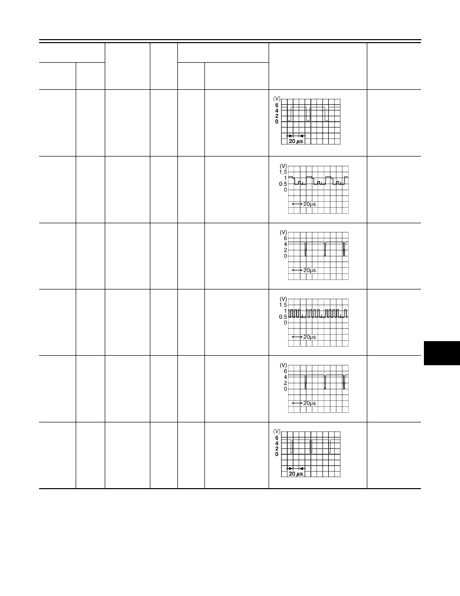
51 (B)
49
RGB area
(YS) signal
Output
ON
Press the“TRIP”
button.
RGB screen is
not shown.
52 (R/W)
47
RGB signal
(G: green)
Output
ON
Select “Display
Diagnosis (DCU)” of
CONFIRMATION/
ADJUSTMENT
function.
Screen looks
reddish.
53 (W)
49
Vertical syn-
chronizing
(VP) signal
Input
ON
–
Operating
screen for audio
and A/C is not
displayed when
showing NAVI
screen.
54 (B)
47
RGB signal
(B: blue)
Output
ON
Select “Display
Diagnosis (DCU)” of
CONFIRMATION/
ADJUSTMENT
function.
Screen looks
yellowish.
55 (R)
49
Horizontal
synchroniz-
ing (HP) sig-
nal
Input
ON
–
Operating
screen for audio
and A/C is not
displayed when
showing NAVI
screen.
56 (G)
49
RGB syn-
chronizing
signal
Output
ON
Press the “TRIP”
button.
NAVI screen is
rolling.
Terminal No.
(Wire color)
Item
Signal
input/
output
Condition
Voltage
(Approx.)
Example of
symptom
+
–
Igni-
tion
switch
Operation
SKIA0162E
SKIA4981E
SKIA4983E
SKIA4982E
SKIA4983E
SKIA0164E