Nissan Pathfinder (2006 year). Manual - part 77
NAVIGATION SYSTEM
AV-107
C
D
E
F
G
H
I
J
L
M
A
B
AV
2006 Pathfinder
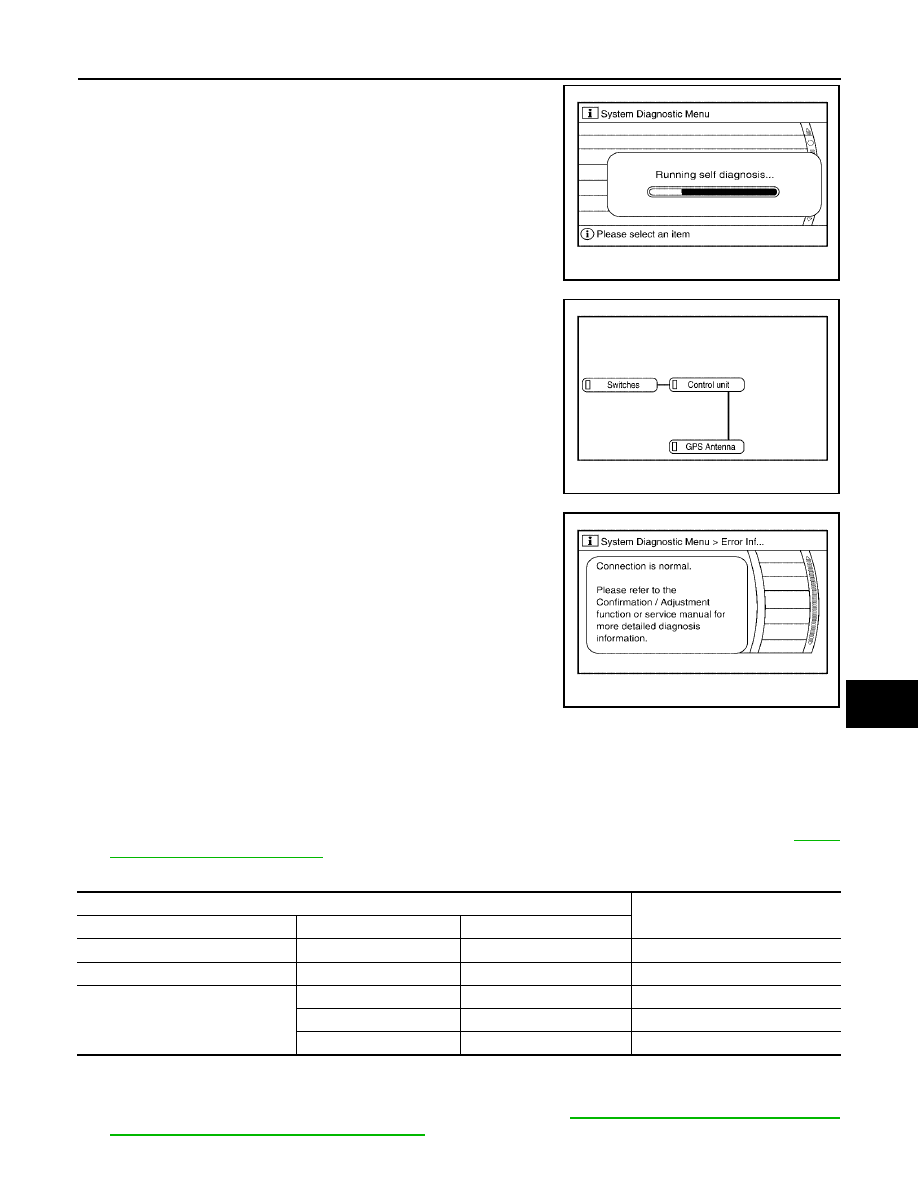
5.
Perform self-diagnosis by selecting the “Self-diagnosis (NAVI)”.
●
Self-diagnosis subdivision screen will be shown and the oper-
ation enters the self-diagnosis mode.
●
A bar graph will be shown on the screen to indicate progress
of the diagnosis.
6.
On the “SELF DIAGNOSIS” screen, each unit name will be col-
ored according to the diagnosis result, as follows.
●
If several malfunctions are present in a unit, color of its switch
on the screen will be either red, yellow, or gray, determined by
the malfunction of the highest priority.
7.
Select a switch on the “SELF DIAGNOSIS” screen and com-
ments for the diagnosis results will be shown.
●
When the switch is green, the following comment will be
shown. “Connection is normal. Please refer to the Confirma-
tion / Adjustment function or service manual for more detailed
diagnosis information."
●
When the switch is yellow, the following comment will be
shown. “Connection to the following unit is abnormal. See the
service manual for further details”.
●
When the switch is red, the following comment will be shown.
“Center Control Unit is abnormal”.
●
When the switch is gray, the following comment will be shown. “Self-diagnosis for DVD-ROM DRIVER
of NAVI was not conducted because no DVD-ROM was available.”
SELF–DIAGNOSIS RESULT
Quick reference table
1.
Select an malfunctioning diagnosis No. in the diagnosis result quick reference table.
2.
Find estimated malfunctioning system in the diagnosis No. table and perform check by referring to
3.
Turn the ignition switch OFF and perform self-diagnosis again.
*: Center Control unit = NAVI control unit
CAUTION:
●
When AV switch has a malfunction, you cannot start. Refer to
AV-147, "Unable to Operate All of AV
Switches (Unable to Start Self-Diagnosis)"
WKIA4440E
Green
: Not malfunctioning.
Yellow
: Cannot be judged by self-diagnosis results.
Red
: Unit is malfunctioning.
Gray
: Diagnosis has not been done.
WKIA4441E
WKIA4442E
Screen switch
Diagnosis No.
Switch color
Center control unit*
GPS antenna
Red
×
1
Gray
×
2
Yellow
×
3
×
4
×
×
5