Nissan Pathfinder (2005 year). Manual - part 438
 

  Index      Manuals     Nissan Pathfinder (2005 year) - Service and Repair Manual


Search            copyright infringement  


Content      ..     436      437      438      439     ..


Nissan Pathfinder (2005 year). Manual - part 438


TROUBLE DIAGNOSIS FOR SYMPTOMS

TF-123

[ATX14B]

C

E

F

G

H

I

J

K

L

M

A

B

TF

2005 Pathfinder

4WD Warning Lamp Does Not Turn ON

EDS001K1

SYMPTOM:

4WD warning lamp does not turn ON when turning ignition switch to “ON”.

DIAGNOSTIC PROCEDURE

1.

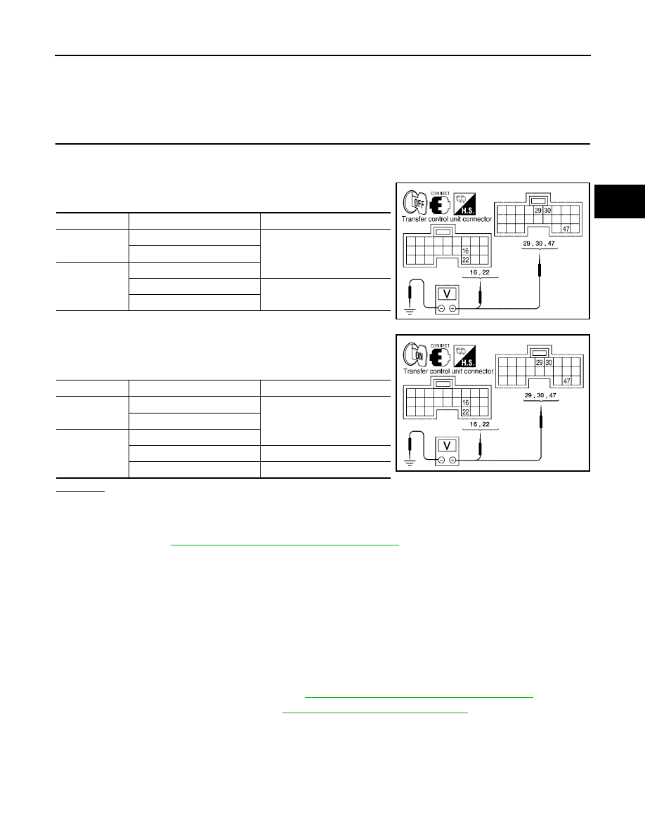
CHECK TRANSFER CONTROL UNIT POWER SUPPLY CIRCUIT

1.

Turn ignition switch “OFF”. (Stay for at least 5 seconds.)

2.

Connect transfer control unit harness connector.

3.

Check voltage between transfer control unit harness connector
terminals and ground.

4.

Turn ignition switch “ON”. (Do not start engine.)

5.

Check voltage between transfer control unit harness connector
terminals and ground.

OK or NG

OK

>> GO TO 2.

NG

>> Check the following. If any items are damaged, repair or replace damaged parts.

10A fuses [No. 21 located in fuse block (J/B) and No. 59 located in the fuse and relay box.
Refer to

PG-4, "POWER SUPPLY ROUTING CIRCUIT"

.

Harness for short or open between battery and transfer control unit harness connector M153
terminals 47.

Harness for short or open between ignition switch and transfer control unit harness connector
M153 terminal 29.

Harness for short or open between battery and transfer shut off relay harness connector E155
terminal 1 and 3.

Harness for short or open between transfer shut off relay harness connector E155 terminal 2
and transfer control unit harness connector M153 terminal 30.

Harness for short or open between transfer shut off relay harness connector E155 terminal 5
and transfer control unit harness connector M152 terminals 16 and 22.

Battery and ignition switch. Refer to

PG-4, "POWER SUPPLY ROUTING CIRCUIT"

.

Transfer shut off relay. Refer to

TF-60, "COMPONENT INSPECTION"

.

Connector

Terminal (Wire color)

Voltage (Approx.)

M152

16 - Ground

0V

22 - Ground

M153

29 - Ground

30 - Ground

Battery voltage

47 - Ground

WDIA0165E

Connector

Terminal (Wire color)

Voltage (Approx.)

M152

16 - Ground

Battery voltage

22 - Ground

M153

29 - Ground

30 - Ground

0V

47 - Ground

Battery voltage

WDIA0166E

TF-124

[ATX14B]

TROUBLE DIAGNOSIS FOR SYMPTOMS

2005 Pathfinder

2.

CHECK TRANSFER CONTROL UNIT GROUND CIRCUIT

1.

Turn ignition switch “OFF”. (Stay for at least 5 seconds.)

2.

Disconnect transfer control unit harness connector.

3.

Check continuity between transfer control unit harness connec-
tor M152 terminals 3 and 6, and M153 terminal 45 and ground.

Also check harness for short to power.

OK or NG

OK

>> GO TO 3.

NG

>> Repair open circuit or short to power in harness or con-

nectors.

3.

CHECK COMBINATION METER POWER SUPPLY CIRCUIT

1.

Turn ignition switch “OFF”. (Stay for at least 5 seconds.)

2.

Disconnect transfer control unit harness connector.

3.

Check voltage between combination meter harness connector
terminal and ground.

4.

Turn ignition switch “ON”. (Do not start engine.)

5.

Check voltage between combination meter harness connector
terminal and ground.

OK or NG

OK

>> GO TO 4.

NG

>> Check the following. If any items are damaged, repair or

replace damaged parts.

10A fuse [No. 14, located in the fuse block (J/B)].
Refer to

PG-4, "POWER SUPPLY ROUTING CIRCUIT"

.

Harness for short or open between ignition switch and combination meter harness connector
M24 terminal 16.

Ignition switch. Refer to

PG-4, "POWER SUPPLY ROUTING CIRCUIT"

.

Continuity should exist.

SDIA2691E

Connector

Terminal (Wire color)

Voltage (Approx.)

M24

16 - Ground

0V

SDIA2762E

Connector

Terminal (Wire color)

Voltage (Approx.)

M24

16 - Ground

Battery voltage

SDIA2763E

TROUBLE DIAGNOSIS FOR SYMPTOMS

TF-125

[ATX14B]

C

E

F

G

H

I

J

K

L

M

A

B

TF

2005 Pathfinder

4.

CHECK HARNESS BETWEEN TRANSFER CONTROL UNIT AND COMBINATION METER

1.

Turn ignition switch “OFF”. (Stay for at least 5 seconds.)

2.

Disconnect transfer control unit harness connector and combination meter harness connector.

3.

Check continuity between the following terminals.

Transfer control unit harness connector M152 terminal 5 and
combination meter harness connector M24 terminal 31.

Also check harness for short to ground and short to power.

OK or NG

OK

>> GO TO 5.

NG

>> Repair or replace damaged parts.

5.

CHECK INDICATOR LAMP CIRCUIT

1.

Connect combination meter harness connector.

2.

Disconnect transfer control unit harness connector.

3.

Turn ignition switch “ON”. (Do not start engine.)

4.

Ground the following terminal using suitable wiring.

Transfer control unit harness connector M152 terminal 5 and
ground.

Does 4WD warning lamp turn on?

OK

>> GO TO 6.

NG

>> Replace combination meter. Refer to

IP-13, "COMBINA-

TION METER"

.

6.

SYMPTOM CHECK

Check again.

OK or NG

OK

>> Inspection End

NG

>> GO TO 7.

7.

CHECK TRANSFER CONTROL UNIT

Check transfer control unit input/output signal. Refer to

TF-38, "Transfer Control Unit Input/Output Signal Ref-

erence Values"

.

OK or NG

OK

>> Inspection End.

NG

>> Check transfer control unit pin terminals for damage or loose connection with harness connector.

If any items are damaged, repair or replace damaged parts.

4WD Shift Indicator Lamp or 4LO Indicator Lamp Does Not Change

EDS001K2

SYMPTOM:

4WD shift indicator lamp or 4LO indicator lamp does not change when switching 4WD shift switch.

Continuity should exist.

SDIA2773E

SDIA2774E

TF-126

[ATX14B]

TROUBLE DIAGNOSIS FOR SYMPTOMS

2005 Pathfinder

DIAGNOSTIC PROCEDURE

1.

CONFIRM THE SYMPTOM

Confirm 4WD shift indicator lamp and 4LO indicator lamp turn on when ignition switch is turned to ON.

Do 4WD shift indicator lamp and 4LO indicator lamp turn on?

YES

>> GO TO 2.

NO

>> Go to

TF-120, "4WD Shift Indicator Lamp and 4LO Indicator Lamp Do Not Turn ON"

.

2.

CHECK SYSTEM FOR 4WD SHIFT SWITCH

Perform trouble diagnosis for 4WD shift switch system. Refer to

TF-65, "4WD Shift Switch"

.

OK or NG

OK

>> GO TO 3.

NG

>> Repair or replace damaged parts.

3.

CHECK SYSTEM FOR WAIT DETECTION SWITCH

Perform trouble diagnosis for wait detection switch system. Refer to

TF-69, "Wait Detection Switch"

.

OK or NG

OK

>> GO TO 4.

NG

>> Repair or replace damaged parts.

4.

CHECK SYSTEM FOR NEUTRAL-4LO SWITCH

Perform trouble diagnosis for neutral-4LO switch system. Refer to

TF-62, "Neutral-4LO Switch"

.

OK or NG

OK

>> GO TO 5.

NG

>> Repair or replace damaged parts.

5.

CHECK SYSTEM FOR ATP SWITCH

Perform trouble diagnosis for ATP switch system. Refer to

TF-116, "ATP Switch"

.

OK or NG

OK

>> GO TO 6.

NG

>> Repair or replace damaged parts.

6.

CHECK SYSTEM FOR 2-4WD SOLENOID

Perform trouble diagnosis for 2-4WD solenoid system. Refer to

TF-93, "2-4WD Solenoid"

.

OK or NG

OK

>> GO TO 7.

NG

>> Repair or replace damaged parts.

7.

CHECK SYSTEM FOR TRANSFER CONTROL DEVICE

Perform trouble diagnosis for transfer control device system. Refer to

TF-84, "Transfer Control Device"

.

OK or NG

OK

>> GO TO 8.

NG

>> Repair or replace damaged parts.

8.

CHECK SYSTEM FOR ACTUATOR MOTOR

Perform trouble diagnosis for actuator motor system. Refer to

TF-73, "Actuator Motor"

.

OK or NG

OK

>> GO TO 9.

NG

>> Repair or replace damaged parts.

TROUBLE DIAGNOSIS FOR SYMPTOMS

TF-127

[ATX14B]

C

E

F

G

H

I

J

K

L

M

A

B

TF

2005 Pathfinder

9.

CHECK SYSTEM FOR ACTUATOR POSITION SWITCH

Perform trouble diagnosis for actuator position switch system. Refer to

TF-80, "Actuator Position Switch"

.

OK or NG

OK

>> GO TO 10.

NG

>> Repair or replace damaged parts.

10.

SYMPTOM CHECK

Check again.

OK or NG

OK

>> Inspection End.

NG

>> GO TO 11.

11.

CHECK TRANSFER CONTROL UNIT

Check transfer control unit input/output signal. Refer to

TF-38, "Transfer Control Unit Input/Output Signal Ref-

erence Values"

.

OK or NG

OK

>> GO TO 12.

NG

>> Check transfer control unit pin terminals for damage or loose connection with harness connector.

If any items are damaged, repair or replace damaged parts.

12.

CHECK TRANSFER INNER PARTS

1.

Disassemble transfer assembly. Refer to

TF-146, "Disassembly and Assembly"

.

2.

Check transfer inner parts.

OK or NG

OK

>> Inspection End.

NG

>> Repair or replace damaged parts.

ATP Warning Lamp Turns ON

EDS001K3

SYMPTOM:

ATP warning lamp turns ON when 4WD shift switch is switched from “4H” to “4LO” or “4LO” to “4H”
with A/T selector lever “N” or “P” position.

DIAGNOSTIC PROCEDURE

1.

CHECK SYSTEM FOR CAN COMMUNICATION LINE

Perform self-diagnosis. Refer to

TF-53, "Self-diagnostic Procedure"

.

Do the self-diagnostic results indicate CAN communication?

YES

>> Perform trouble diagnosis for CAN communication line. Refer to

TF-116, "CAN Communication

Line"

.

NO

>> GO TO 2.

2.

CHECK SYSTEM FOR 4WD SHIFT SWITCH

Perform trouble diagnosis for 4WD shift switch system. Refer to

TF-65, "4WD Shift Switch"

.

OK or NG

OK

>> GO TO 3.

NG

>> Repair or replace damaged parts.

3.

CHECK SYSTEM FOR PNP SWITCH SIGNAL

Perform trouble diagnosis for PNP switch signal system. Refer to

TF-72, "PNP Switch Signal (TCM)"

.

OK or NG

OK

>> GO TO 4.

NG

>> Repair or replace damaged parts.

TF-128

[ATX14B]

TROUBLE DIAGNOSIS FOR SYMPTOMS

2005 Pathfinder

4.

CHECK SYSTEM FOR ATP SWITCH

Perform trouble diagnosis for ATP switch system. Refer to

TF-116, "ATP Switch"

.

OK or NG

OK

>> GO TO 5.

NG

>> Repair or replace damaged parts.

5.

CHECK HARNESS BETWEEN TRANSFER CONTROL UNIT AND COMBINATION METER

1.

Turn ignition switch “OFF”. (Stay for at least 5 seconds.)

2.

Disconnect transfer control unit harness connector and combination meter harness connector.

3.

Check continuity between the following terminals.

Transfer control unit harness connector M152 terminal 15 and
combination meter harness connector M24 terminal 21.

Transfer control unit harness connector M152 terminal 40 and
combination meter harness connector M24 terminal 1.

Also check harness for short to ground and short to power.

OK or NG

OK

>> GO TO 6.

NG

>> Repair or replace damaged parts.

6.

CHECK ATP WARNING LAMP CIRCUIT

1.

A/T selector lever "P" position.

2.

Connect combination meter harness connector and transfer control unit harness connector.

3.

Disconnect ATP switch harness connector.

4.

Ground the following terminal using suitable wiring.

5.

Turn ignition switch “ON”. (Do not start engine.)

ATP switch harness connector F55 terminal 8 and ground.

Does indicator lamp turn on?

OK

>> GO TO 7.

NG

>> Replace combination meter. Refer to .

IP-13, "COMBI-

NATION METER"

.

Continuity should exist.

SDIA2768E

40 TO 1: Continuity should
not exist.

1 to 40: Continuity should
exist.

SDIA2770E

SDIA2769E

TROUBLE DIAGNOSIS FOR SYMPTOMS

TF-129

[ATX14B]

C

E

F

G

H

I

J

K

L

M

A

B

TF

2005 Pathfinder

7.

SYMPTOM CHECK

Check again.

OK or NG

OK

>> Inspection End.

NG

>> GO TO 8.

8.

CHECK TRANSFER CONTROL UNIT

Check transfer control unit input/output signal. Refer to

TF-38, "Transfer Control Unit Input/Output Signal Ref-

erence Values"

.

OK or NG

OK

>> GO TO 9.

NG

>> Check transfer control unit pin terminals for damage or loose connection with harness connector.

If any items are damaged, repair or replace damaged parts.

9.

CHECK TRANSFER INNER PARTS

1.

Disassemble transfer assembly. Refer to

TF-146, "Disassembly and Assembly"

.

2.

Check transfer inner parts.

OK or NG

OK

>> Inspection End.

NG

>> Repair or replace damaged parts.

4LO Indicator Lamp Repeats Flashing

EDS001K4

SYMPTOM:

4LO indicator lamp keeps flashing.

DIAGNOSTIC PROCEDURE

1.

CONFIRM THE SYMPTOM

1.

Set 4WD shift switch to “2WD”.

2.

Move vehicle forward and backward, or drive straight increasing or decreasing under 20 km/h (12 MPH).

Dose 4WD shift indicator lamp keep flashing?

YES

>> GO TO 2.

NO

>> Inspection End.

2.

CHECK SYSTEM FOR WAIT DETECTION SWITCH

Perform trouble diagnosis for wait detection switch system. Refer to

TF-69, "Wait Detection Switch"

.

OK or NG

OK

>> GO TO 3.

NG

>> Repair or replace damaged parts.

3.

CHECK SYSTEM FOR NEUTRAL-4LO SWITCH

Perform trouble diagnosis for neutral-4LO switch system. Refer to

TF-62, "Neutral-4LO Switch"

.

OK or NG

OK

>> GO TO 4.

NG

>> Repair or replace damaged parts.

4.

SYMPTOM CHECK

Check again.

OK or NG

OK

>> Inspection End.

NG

>> GO TO 5.

TF-130

[ATX14B]

TROUBLE DIAGNOSIS FOR SYMPTOMS

2005 Pathfinder

5.

CHECK TRANSFER CONTROL UNIT

Check transfer control unit input/output signal. Refer to

TF-38, "Transfer Control Unit Input/Output Signal Ref-

erence Values"

.

OK or NG

OK

>> GO TO 6.

NG

>> Check transfer control unit pin terminals for damage or loose connection with harness connector.

If any items are damaged, repair or replace damaged parts.

6.

CHECK TRANSFER INNER PARTS

1.

Disassemble transfer assembly. Refer to

TF-146, "Disassembly and Assembly"

.

2.

Check transfer inner parts.

OK or NG

OK

>> Inspection End.

NG

>> Repair or replace damaged parts.

4WD Warning Lamp Flashes Rapidly

EDS002FJ

SYMPTOM:

While driving, 4WD warning lamp flashes rapidly.

NOTE:
Rapid flashing: 2 times/second

DIAGNOSTIC PROCEDURE

1.

CHECK TIRE

Check the following.

Tire pressure

Wear condition

Longitudinal tire size (There is no difference between longitudinal tires.)

OK or NG

OK

>> GO TO 2.

NG

>> Repair or replace damaged parts.

2.

CHECK 4WD WARNING LAMP

Stop the vehicle and allow it to idle for a short period of time.

Does the 4WD warning lamp stop flashing?

YES

>> Inspection End.

NO

>> GO TO 3.

3.

CHECK TRANSFER FLUID TEMPERATURE

Perform trouble diagnosis for transfer fluid temperature system. Refer to

TF-104, "Transfer Fluid Temperature"

.

OK or NG

OK

>> GO TO 4.

NG

>> Repair or replace damaged parts.

4.

SYMPTOM CHECK

Check again.

OK or NG

OK

>> Inspection End.

NG

>> GO TO 5.


Content      ..     436      437      438      439     ..