Nissan Pathfinder (2005 year). Manual - part 393
REAR SUSPENSION ASSEMBLY
RSU-7
C
D
F
G
H
I
J
K
L
M
A
B
RSU
2005 Pathfinder
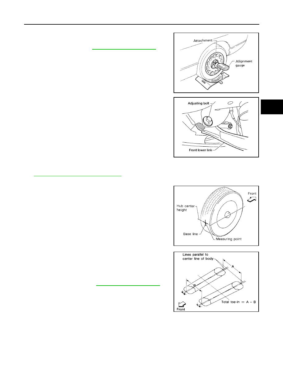
CAMBER
1.
Measure camber of both the right and left wheels with a suitable
alignment gauge and adjust as necessary to specification.
2.
If outside of the specified value, adjust the camber using the
adjusting bolt in the front lower link.
CAUTION:
After adjusting the camber then check the toe-in.
NOTE:
Camber changes about 0
°
5' with each graduation of the adjust-
ing bolt.
3.
Tighten the adjusting bolt nuts to specification.
TOE-IN
1.
Bounce the rear of the vehicle up and down two to three times to stabilize the vehicle height. Refer to
RSU-22, "Wheelarch Height (Unladen* )"
.
2.
Push the vehicle straight ahead about 5 m (16 ft).
3.
Put a mark on the base line of the tread (rear side) of both of the
tires at the same height as the center of the hub. These will be
the measuring points.
4.
Measure the distance “A” (rear side) across from tire to tire.
5.
Push the vehicle slowly ahead to rotate the wheels 180
°
degrees (a half turn).
If the wheels are rotated more than 180
°
degrees (a half turn),
then repeat the above steps. Never push the vehicle backward.
6.
Measure the distance “B” (front side) across from tire to tire.
Camber
: Refer to
.
SRA096A
LEIA0041E
SFA614B
Total toe-in
: Refer to
.
SFA234AC